Category: Articles

Stay updated with the latest Air flow meter market news, Global Market Share, Trends, Analysis, and Forecasts with LEOMI Instruments.

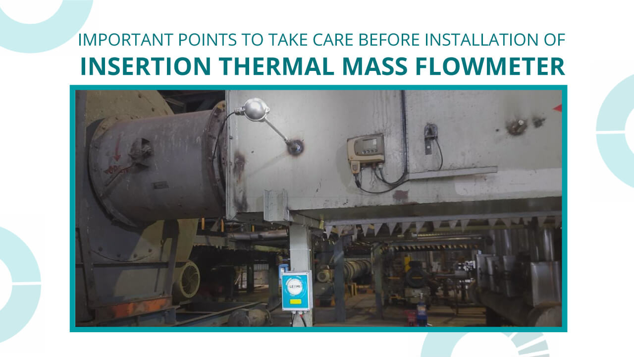
  • Important Points to Take Care Before Installation of Insertion Thermal Mass Flow meter

    Important Points to Take Care Before Installation of Insertion Thermal Mass Flow meter

    points to take care before installation of insertion thermal mass flowmeter

    Application Study

    To conduct a site survey for understanding what is the purpose of gas flow measurement based on process conditions. E.g. Flue Gas stack flow measurement in Coal based Thermal Power plant.

    Insertion Thermal Mass Flow Meter Process Conditions

    Confirm fluid properties as below for optimum selection :

    • Standard Gas or gas mixture (total % proportion)
      Is it a real gas such as nitrogen or a gas mixture such as biogas with 75%methane + 15%CO2 + 5% Nitrogen + 3% water vapor + 2%H2S.
    • Specific gravity or Density or molecular weight
      Standard gas such as Nitrogen has specific gravity :1.25 or density :1250 Kg/Nm3
    • Flow rates (minimum, operating, maximum) based on customers process conditions. Flow rates should be at specific temperature & pressure conditions. E.g. Nm3/hr (DIN1343 – 0⁰C & 1.01325bar), Sm3/hr (Standard 20⁰C &1.01325bar OR ISO2533 15⁰C &1.01325bar ) or Actual m3/hr as per operating conditions.

    temperature & static pressure

    • Static pressure (minimum, operating and maximum in barg or suitable units).
      Static pressure of the gas flowing in the pipeline or duct.
    • Temperature (minimum, operating & maximum ⁰C )
      Temperature of the gas flowing in the pipeline or duct.
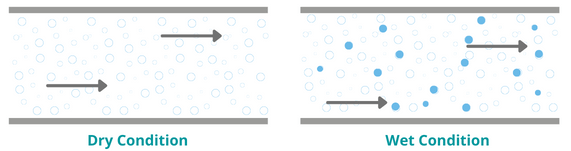
    • Gas conditions such as dry or wet gas or any details of RH% of gas flowing.

    • Gas contains dust or dirt if possible dust concentration in ppm
    • Gas corrosion properties or suitable material compatibility with wetted sensor part
    • Hazardous or Non Hazardous. Identify whether the area of use is hazardous than protection class, zone & gas group classification is needed. ( E.g. Zone I or II Gas group IIA IIB IIC etc). For Non-hazardous Ingress protection such as IP65,IP66,IP67 needed for enclosure & sensor probe housing.

    Mounting

    Confirm accurately below:

    • Pipe dimension: Measure Pipe OD, ID and Thickness OR confirm pipe schedule Sch40,Sch80 etc OR If available Pipe class Class A, Class B or Class C.
    • Duct Size & Type: If Duct is in use check whether it is Square or Rectangular and measure dimensions accurately & Wall thickness
    • Installation location & Mounting Type: Check plant site and identify suitable installation location having desired straight length available. If straight length not available discuss possible practical solutions.
    • With or without isolation valve: If an application demands an isolated sensor probe while running, the process isolation valve needs to be installed or else not.

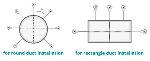
    Orientation

    Identify sensor probe mounting based on space available nearby pipe or duct.

    • Horizontal
    • Vertical
    • Angular based on space available nearby pipe or duct.

    round and rectangle duct installation

    Recommendations

    Check additional points as below:

    • Upstream & Downstream straight length available at mounting site.
    • Power supply conditions
  • Why is the Actual Mass Flow Rate Important in Gas Flow Measurement?

    Why is the Actual Mass Flow Rate Important in Gas Flow Measurement?

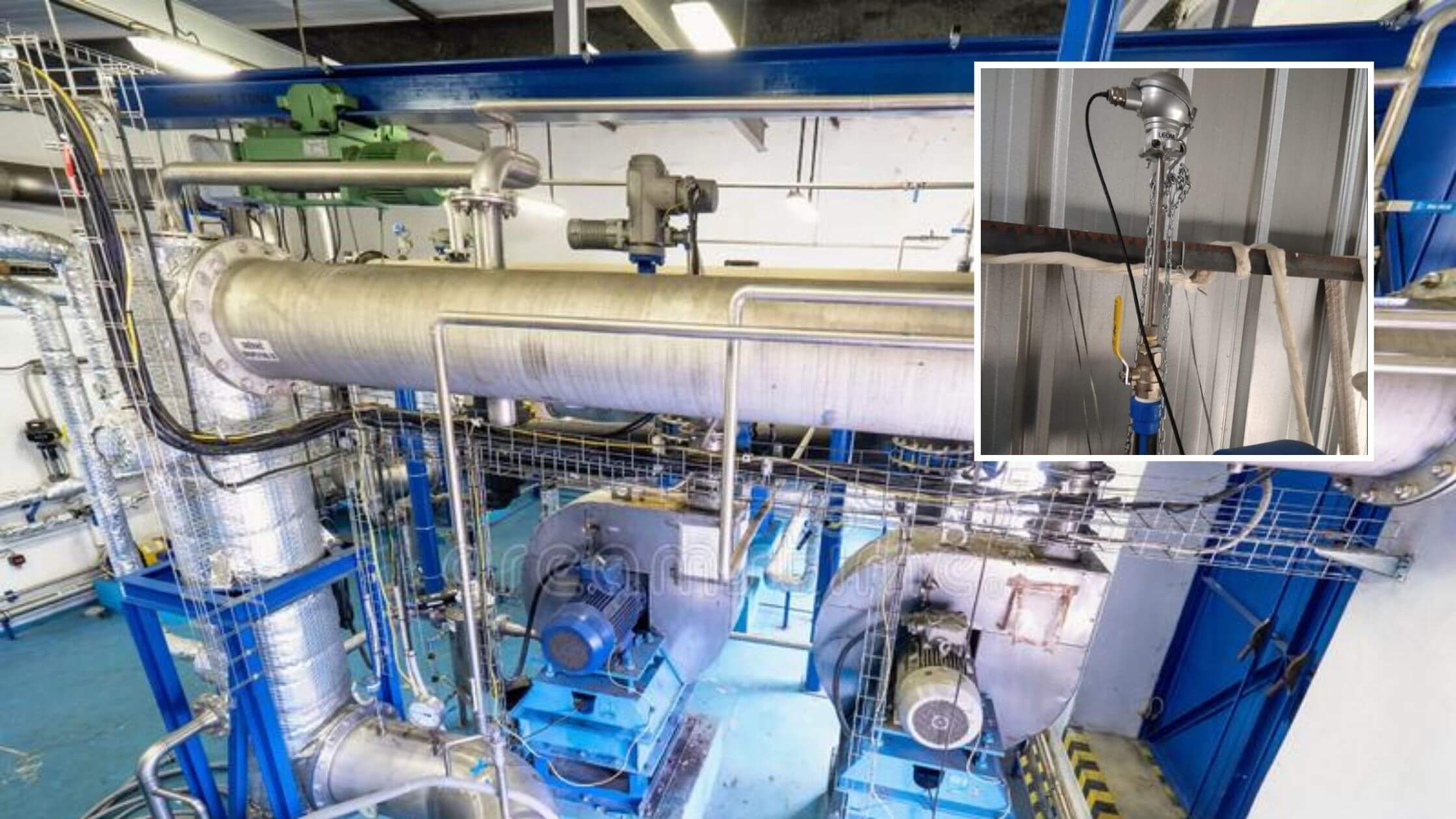
    Importance of Actual Mass Flow Rate in energy plant

    Gas mass flow measurement is always a challenge in process conditions. There are very few flow technologies available for achieving it such as Coriolis, Calorimetric ( Thermal Mass) etc..Gas volume varies with respect to temperature and pressure as per Charles & Boyle’s law but Gas mass remains constant. This is the main reason to measure actual mass flow rate is important to monitor in processes.

    Let’s understand the difference between Standard & Actual Flow Rate first.

    Standard Flow Rates

    Standard flow rate is a flow rate of gas at specific pressure and temperature conditions. It is dependent on pressure and temperature conditions. It is termed as Standard volumetric
    (Sm3/hr or SCFM) or Standard Mass flow rate (Kg/hr at specific standard conditions).

    There are different standards conditions used internationally such as :

    • ISO2533 (1.01325bara @ 15°C );
    • DIN 1343 ( 1.01325bar @ 0°C);
    • Standard (1.01325bar @ 20°C) etc.
      (above with 0% relative humidity conditions generally or sometime varying conditions )

    Actual Flow Rates

    Actual Flow rate is a flow rate of gas at different pressure and temperature conditions, It is independent of pressure and temperature conditions. It is termed as Actual Volumetric ( Am3/hr or ACFM ) or Actual Mass Flow Rate (Kg/hr at actual process conditions)

    Importance of Actual Mass flow rate measurement

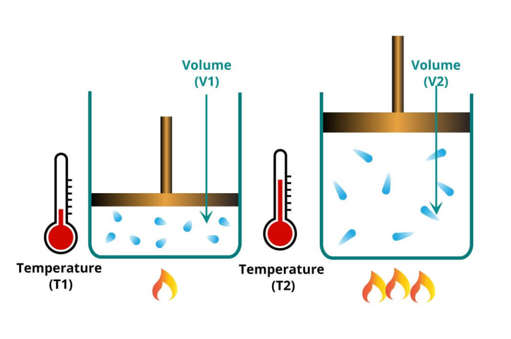
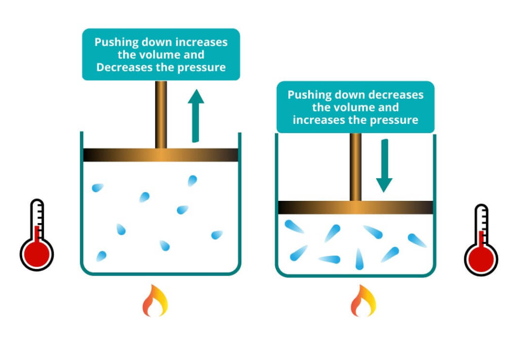
    As per Charles Law states that at constant pressure ideal gas volume increases with increase in temperature or gasses expands when heated.

    Boiling water at different temperatures

    And Bolye’s Law states that at a constant temperature ideal gas volume is inversely proportional to pressure applied on the gas. It implies at constant temperature volume increases when pressure decreases and gas volume decreases when pressure increases.

    Pressure change by moving changing volume

    From above laws we understand that measuring volumetric gas flow rate gives a huge measurement error due to the fact that gas volume varies with changing temperature & pressure conditions.

    Therefore, we must measure the actual mass flow rate of gas for an accurate measurement for controlling the process conditions.

    Leomi 587 Insertion Thermal Mass Flow Meter for Actual Mass / Volume Flow Rate measurement is developed considering the process industry’s real requirement for optimizing process conditions with accurate and real measurement.

  • LEOMI 587 – A Perfect Choice for Compressed Air Auditor

    LEOMI 587 – A Perfect Choice for Compressed Air Auditor

    Leomi 587 mass flow meter for compressed air auditor

    Modern industries have to provide an efficient and productive manufacturing operation where compressed air plays an important role as utility after water. Compressed air is an important medium for transfer of energy in many industrial processes. It has wide usage in manufacturing processes such as pneumatic conveying of bulk materials, pneumatically operated machinery such as Airjet looms, aerated bottling plant, spray paint booths, pet bottle machinery, printing machinery, CNC machines, HVAC controls etc & power tools such as valves, drills, air hammers, wrenches and many more for process automation.

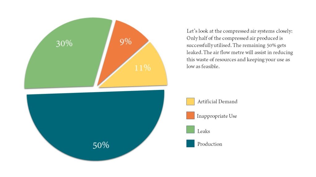
    Compressed air is an invisible energy, It comprises almost 10% to 30% of energy cost in many of the process industries.

    Automobiles, Textiles, Pharmaceuticals, Food and Beverages are some of the major consumers of compressed air.

    Considering the above facts, An efficient selection of the right compressor type and capacity is quite important. Compressed air piping systems must be designed for best efficiency and optimization. And a plant operator must ensure elimination of leakages, misuse, overpressurization, peak load management and reduce pressure drop for efficient compressed air systems.

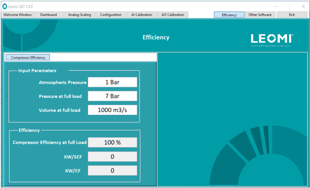
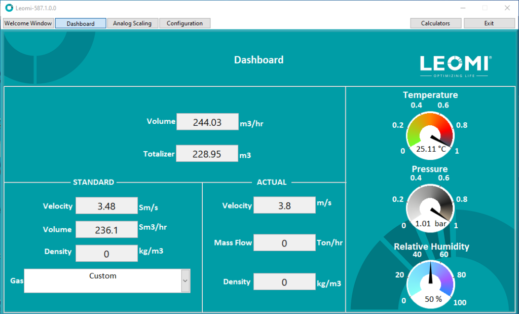
    For efficient compressed air systems, Compressed air flow rate in terms of free air delivery (FAD), discharge pressure, temperature, compressor’s actual power measurement is important. In-order to achieve this goal Leomi- 587 An Insertion Thermal Mass Flowmeter is developed. A perfect tools which will measure & record with in-built USB datalogger Actual CFM ( FAD) corrected with actual relative humidity (%); Pressure, Temperature, Actual power(KW) and also calculates full load efficiency, CFM/KW with a custom built software and provides an excel report of all the parameter which makes life easier for an energy auditor.

    IMPORTANT FEATURES:

    • Measuring actual mass/volume flow rate
    • Suitable to 15mm to 10000mm pipe sizes
    • Probes with Ø=12mm/20mm(HC276) & Length up-to 2000 mm available
    • Better accuracy < ±2%RD of actual mass flow rate
    • Upto 4 user selectable analogue input such as pressure, temperature, power or RH% etc.
    • Turndown ratio 100:1 or better
    • Accurate measurement over temperature ranges upto 400°C
    • In-built data storage with USB 2.0 in csv format for input parameters
    • In-built auto purging system for sensor cleaning
    • Ideal for customized flow control applications with PC software

    Leomi 587 Software:

    LEOMI 587 COMPRESSOR EFFICIENCY
    LEOMI 587 SOFTWARE DASHBOARD
    IN-BUILT USB DATA LOGGING

    Click here to know more in detail about Leomi 587 Actual Mass Flow Meter.

  • Flow Measurement In Water & Wastewater Industries

    Flow Measurement In Water & Wastewater Industries

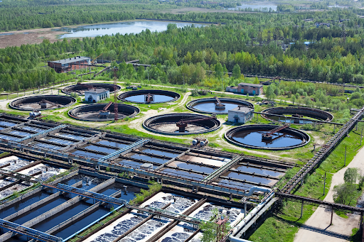
    Flow measurement in wastewater treatment

    Wastewater treatment plant automation is getting crucial day by day due to complex processes & un-even wastewater quality due to modern lifestyles having a wide variety of contaminants. There are many important parameters to be monitored to optimize the purification process. Wastewater treatment mainly depends on the loads of wastewater and aeration process. Various flow measurement techniques are now emerging with respect to fluid & process conditions.

    Where is Wastewater Treatment required?

    The wastewater treatment process needs accurate, reliable flow measurements for defining treatment conditions. Major areas where Flow measurement in wastewater treatment is required are :

    • Influent wastewater (Raw wastewater) from drainage or city sewage
    • Primary treated wastewater
    • Secondary treated wastewater
    • Aeration air in aeration lane for optimizing Dissolved oxygen (DO)
    • Chlorine dosing precise monitoring
    • Precise corrosion inhibitor dosing

    Flow measurement technology

    Flow measurement technologies involved in wastewater treatment plant processes are as below

    • Electromagnetic Flowmeter (Full Bore Or Insertion Type)
    • Non-Contact Ultrasonic Flowmeter
    • Insertion Thermal Mass Flowmeter
    • Open Channel Ultrasonic  Flow meter
    • Coriolis Flowmeter
    • Orifice Flowmeter

    Above are major flow measurement technologies used for monitoring & controlling wastewater treatment processes.

    Let’s describe in detail each flow measurement technique above with its advantages and limitations related to its application.

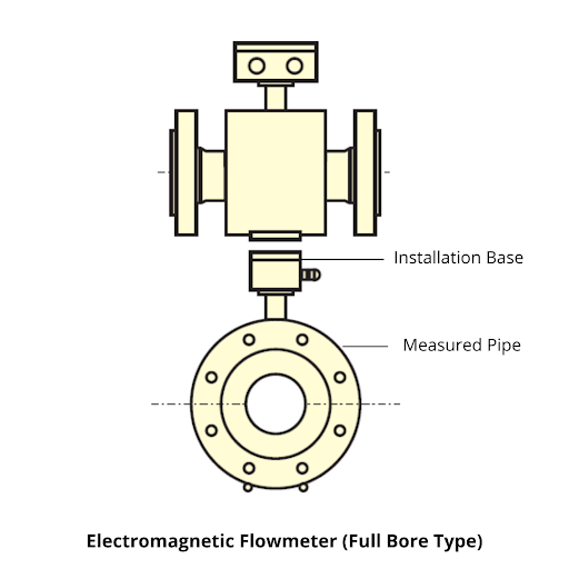
    1. Full Bore Type Electromagnetic Flow Meter

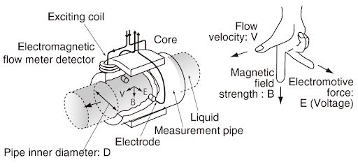
    Electromagnetic flow meters work by using Faraday’s Law of induction. Inside an electromagnetic flow meter, there is an electromagnetic coil that generates a magnetic field, and electrodes that capture electromotive force(voltage). Due to this, although it may appear as if there is nothing inside the flow pipe of an electromagnetic flow meter, flow can be measured.

    Under Faraday’s law of induction, moving conductive liquids inside of a magnetic field generates an electromotive force (voltage) in which the pipe inner diameter, magnetic field strength, and average flow velocity are all proportional. In other words, the flow velocity of liquid moving in a magnetic field is converted into electricity. (E is proportional to V × B × D)

    Flow measurement in water & wastewater industries 2

    As the flow changes, the electromotive force (voltage) captured by the electrodes changes as follows.

    Advantages

    • Is True Volumetric Liquid flow measurement independent of temperature, pressure, density, viscosity & velocity profile
    • Improves reliability with No moving parts with negligible pressure drop
    • Works well even in solid slurries with air bubbles with a noise suppression circuit
    • Excellent for flow measurement of  Sewage water & slurries, Raw Water, Effluent water, etc.

    Limitations

    • Unable to detect liquids with low electrical conductivity (<1?siemens/cm) such as Hydrocarbons & Solvent etc.
    • For large pipe diameters, it is more costly than the Ultrasonic flowmeter
    • Contact type flow technology has to wear & fouling of liners and electrodes.

    2. Insertion Electromagnetic Flowmeter

    Insertion Electromagnetic flowmeters are an economic alternative to full bore flowmeters. They consist of an electromagnetic coil mounted on the end of the sensing probe. It is an alternative for economical installation for large pipes in existing water distribution systems where provision for flow metering was not originally made. The assembly can be installed in existing pipelines without the need for major excavations or alterations to pipe work normally associated with the installation of full electromagnetic flowmeters.

    Advantages

    • Works well for Water distribution piping,
    • Excellent and economical for large pipe diameters from 200mm to 2000mm
    • Low cost of installation and easy sensor isolation.

    Limitations

    • Lower accuracy (2%)  than full bore electromagnetic flowmeters
    • Not suitable for pipe diameter less than 200mm
    • Not suitable for liquids with high solid impurities

    Above are some highlights on one of the flow measurement technologies widely used in Water & Wastewater industries in helping in monitoring and controlling wastewater, raw water etc. Will come back with another important flow technology in an upcoming article.

    Conclusion

    Electromagnetic flow meter is proven flow technology for liquid flow measurement with long term reliability and accuracy. There are other alternatives emerging to compete with where existing technology has limitations in  performance and initial cost is a concern.

    If you want to learn more about this subject please contact us at  sales@leomi.in

  • Types of Thermal Mass Flowmeter Technologies

    Types of Thermal Mass Flowmeter Technologies

    Types-of-Thermal-Mass-Flow-Meter-Technologies leomi

    Within this blog, we will discuss the different types of thermal mass flowmeter technologies. Thermal mass flowmeters operate on the principle where a heat source is applied to the inlet of the mass flow meter and is then transmitted from one part of the device to another, increasing in temperature (gain an amount of q) based on its thermal resistance.

    The change in temperature as a function of time causes a corresponding change in thermal conductance (change in convective heat transfer coefficient h). As fluid flows through a pipe it changes its speed due to frictional forces and if there is a thermocouple placed at various points within this pipe can determine how much varying thermal power dissipation occurs within that length by relating it back to a known conduit’s temperature gradient.

    Let us discuss the types of thermal mass flowmeters:

    1. Insertion Thermal mass flow meter

    if we have large pipes and don’t want to cut them, then maybe we can use an insertion thermal mass flow sensor. Rather than cutting the pipe, an insertion sensor is inserted into the pipe between two flanges. This one’s easy to install, comes in different sizes and measures the heat of flowing gas. Therefore it doesn’t require a calibration gas, has no moving parts, is unaffected by shock cycling and vibration.

    To find out the total mass flow within the pipe, this sensor factors in the flow rate, compensation and cross-section of your pipe and pressure drop across a specified range by using carefully selected numerical algorithms that are run on a microcontroller. When we scale out a new insertion sensor, we need to make sure that it goes in line with a length of pipe where there won’t be any measurement problems such as where the customer had entered data for the wrong size pipe or inserted the sensor incorrectly.

    2. Bypass Thermal mass flow meter

    Below you can see two names for this device. We call it either a bypass flow meter or a capillary tube flow meter. This type has a laminar flow element and includes an inlet and outlet for the capillary tube where the fuel flows during its cycle. The capillary tube houses all the components of the system, including the transducer and heating coil, but keep in mind that each vendor can have their own variation of it. For example, some may provide up to 3 sensors while others may use 2 heating systems depending on what their design offers.

    This permits you to get more information out of your fuel data such as oxygen content to help determine whether there is any contamination present during transport or storage.

    3. Inline Thermal mass flow meter

    This product has a lightweight, yet aerodynamic shape. It combines the advanced sensor and transmitter in patented packaging. It contains several components such as aluminum, plastic, and fiberglass composites. Due to its cylindrical design, this shell gives the thermal dispersion required at different speeds.

    Why insertion thermal mass flow meter is a better choice?

    Insertion Thermal Mass Flow Meter is a widely used process instrument that is used for measuring volumetric flow rate and thermal conductivity of the materials that are flowing through the process. The fact that an Insertion Thermal Mass Flow meter is a type of thermal mass flow meter, which is thermally compensated for temperature effects in process flow systems, makes it ideal for detecting process flow deviations.

    Moreover, Insertion Thermal Mass Flowmeter is a one-time measurement and substitutes the direct reading of flow rate from multiple instruments. Originally developed for the pharmaceutical industry, it was widely adapted to process equipment such as mixing chambers, reactors, and distillation columns over time.

    Thermal mass flow meters are mainly used in large volume process equipment where the measured temperature change is sufficiently small to be quantifiable. While Insertion Thermal Mass Flowmeter can only provide a reliable estimate of thermal conductivity which varies with time during certain processes, it may give more accurate measurements due to its ability to capture steady-state conditions than other instruments such as paddle wheel meters or rotameters during certain processes. This makes it a great choice for system control, detection of deviations, and measuring plant improvements related to mass flow rate.

    Leomi’s Insertion Thermal Mass flowmeter

    Leomi aims to optimize everyday life with a higher standard of living by manufacturing high-quality Thermal mass flow meters with years of industry experience. Leomi combines decades of experience at Softflow.de in the field of thermal flow measurement and provides reliable meters for customers worldwide!

    Leomi thermal mass flowmeter offer benefits such as:

    • No moving parts, robust metallic construction, and direct mass flow measurement of gases
    • No pressure drop which saves energy against other conventional flowmeters
    • The highest turn down-ratio better than 100:1 provides high sensitivity helps in leak detection
    • High accuracy <±1.5% and resolution against conventional flow meters.
    • Designed up to 400⁰C operating temperature and pressure up to 16bar or higher.
    • Easily cleanable sensor & No significant effect of moisture like thin-film sensor does.
    • Can work in dirty or wet gas environments with accessories
    • Adjustable in various pipe sizes and versatile for different gas and mixtures.
    • Digital controlled with No drift and long term mechanically stable design

    LEOMI’s technical team is continuously working on researching different gas mass flow measurement solutions for various industries that can be implemented while keeping in mind both process and industrial standards.

    Request to kindly write us your inquiry related to the above application and will happy to assist with flow solutions at our best. For more information, log on to https//www.leomi.in & follow us on our LinkedIn page for more updates.

  • PROVIDING FLOW METER TECHNOLOGY WITH IN-HOUSE CALIBRATION

    PROVIDING FLOW METER TECHNOLOGY WITH IN-HOUSE CALIBRATION

    The global flow meter manufacturing industry grew to $8.9 billion in 2020, and it is projected to grow at a CAGR of 5.70 percent till FY2028. The market in India is also expected to see considerable growth due to developments in process automation in various industry core sectors such as Power, water management, chemicals, steel & cement, and more. The global flow meter manufacturing industry grew to $8.9 billion in 2020, and it is projected to grow at a CAGR of 5.70 percent till FY2028.

    The market in India is also expected to see considerable growth due to developments in process automation in various industry core sectors such as Power, water management, chemicals, steel & cement, and more.The global flow meter manufacturing industry grew to $8.9 billion in 2020, and it is projected to grow at a CAGR of 5.70 percent till FY2028. The market in India is also expected to see considerable growth due to developments in process automation in various industry core sectors such as Power, water management, chemicals, steel & cement, and more.

    However, the flow meter industry demands fine-tuning of its process& factory automation which requires products with high accuracy along with a reasonable price range. Manish S. Patel, Director, LEOMI, says, “The primary factor that sets our company apart from the rest of the players in the High-quality Thermal mass flow meter engineered in In­dia for process air and gas flow measurement with various customization options. It is made with German technolo­gy by transfer from softflow.de and has a robust design with a proven track record globally for more than 20 years. We have installed India’s first fully automatic In-house calibration facility & in-house electronic development which provides quick service support to the customers with an affordable pricing range”.


    flow meter manufacturers

    CUSTOMIZED & ENGINEERED PRODUCTS

    Manish adds, “There are large requirements of quality in­ instrumentation with high accuracy and reliability which are currently not available in India forcing the companies to im­port from other countries. Our priority at Leomi is the development of our products into an application based on the expectations of the core sector Industries that we serve, such as power plants and steel & cement as both these industries require customized and engineered products with high accuracy and reliability for their operations. We ensure the quality of our products by meeting all the international standards which are crucial for a product of this type and also helps in exceeding client expectations on performance and reliability”.

    LEOMI started the commissioning of its project along with the establishment of its manufacturing facilities in 2019. It had also recorded a substantial amount of growth in the nuclear, thermal power, steel & textile sector Manish high­ lights, “There is still a lot of room for growth in the Thermal Power sector for flue gas flow measurement and also in the corrosive process gas emissions. We have also exported to Germany, Vietnam, Nigeria to name a few for compressed air and gas” LEOMI is also a registered Start-up India company having an ISO 9001:2015 certification which is a testament to their excellence.

    APPLICATION-ORIENTED PRODUCTS

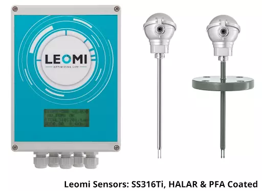
    LEOMI offers flow meter products that have different types of sensor construction such as stainless steel, Hastelloy C276, HALAR & PFA coatings for a wide range of applications in various industries. The Insertion type of flow meters can be used in an adjustable and versatile manner which is used to monitor multiple locations with a wide temperature range up to 400°C. LEOMI also provides inline flow meters for permanent installation for systemic inspection.

    Manish emphasizes, “Currently our company is working on projects in the power sector which includes the nuclear en­ energy, thermal power generation and for the municipal corpo­ration sewage treatment plant in the aeration air, landfill gas monitoring in the solid waste management process, biogas monitoring process in the food and starch industry.

    LEOMI has developed a perfect tool for compressed air monitoring & recording for energy auditors for conservation initiatives with Thermal mass flowmeter”.

    AIMING FOR OPTIMIZATION

    Manish concludes, “The tagline of our company is ‘Opti­mizing Life’ as a central idea for developing products and solutions which help in optimization of process and equip­ment. Optimization helps in energy conservation in various process industries.

    The company also works on developing import substitute technology products which will support the India program for becoming ATMANIRBHAR (self-re­ learned) by reducing the dependency of importing reliable equipment from other countries”.

  • EMERGING FLOW MEASUREMENT SOLUTIONS FOR AIR AND GAS APPLICATIONS FROM LEOMI INSTRUMENTS

    EMERGING FLOW MEASUREMENT SOLUTIONS FOR AIR AND GAS APPLICATIONS FROM LEOMI INSTRUMENTS

    air flow meter in India

    Current market conditions demand superior and reliable products that are competitively priced. This implies industries improve the overall efficiency of equipment & plant processes and simultaneously conserve energy for achieving desired results. Flow measurement is becoming crucial for conserving energy for various utility measurements such as water, compressed air, natural gas, etc. Flow measurement is also important for various other process gases for emission controls. With strict emission norms, process efficiency needs to be tightly controlled where flow measurement is the ultimate requirement.

    LEOMI An ISO-9001:2015 certified & Start-up India recognized company.

    Leomi aiming for “Optimizing Life” has identified various industrial applications helping in overall process optimization and energy conservation by manufacturing high quality and reliable Thermal mass flow meters with a technical collaboration with Softflow.de which has more than 20 years of proven experience in this field. Leomi has also installed India’s first fully automatic wind tunnel for In-house calibration of Insertion thermal mass flowmeter and various velocity-based instruments.

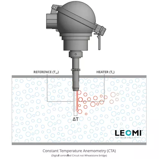
    Leomi Insertion thermal mass flow meter design is based on Constant Temperature Anemometry combined with digital precision over temperature control. The physical principle of thermal dispersion from a heated element to the ambient medium (example: air or gases). This is affected by the velocity, density (temperature and pressure), and by the characteristic of the medium. The amount of needed energy is a function of the temperature difference ∆T and the mass flow.

    Gas flowing through two RTD Pt-100 one reference (Tref) and the other Heater (Th). The temperature difference (over-temperature) ∆t between the reference sensor (medium temperature) and the heater sensor is controlled constantly. As per King’s Law, the higher the mass flow rate, the higher the cooling effect of the heater sensor, thus higher the power required to maintain the differential temperature constant. Therefore, the heater power is proportional to the gas mass flow rate. (As per figure shown)

    Leomi-compressed-air-flow-meter.

    Leomi Thermal mass flow meter offer benefits such as:

    • No moving parts, robust metallic construction, and direct mass flow measurement of gases
    • No pressure drop which saves energy against other conventional flowmeters
    • The highest turn down-ratio better than 100:1 provides high sensitivity helps in leak detection
    • High accuracy <±1.5% and resolution against conventional flow meters.
    • Designed up to 400⁰C operating temperature and pressure up to 16bar or higher.
    • Easily cleanable sensor & No significant effect of moisture like thin-film sensor does.
    • Can work in dirty or wet gas environments with accessories
    • Adjustable in various pipe sizes and versatile for different gas and mixtures.
    • Digital controlled with No drift and long term mechanically stable design

    Applications where Leomi product innovations have been successfully used:

    • Compressed air flow, pressure, dew-point, power monitoring & logging for energy audits, which provides complete compressor’s data with overall efficiency and able to identify leakages and conserve energy.
    • Flue gas & combustion air flow measurement for stack gas for emission controls having various features to the suits power plant and industrial furnaces needs
    • Aeration basin airflow & dissolved oxygen control system in the wastewater treatment plant
    • Natural gas overall utility monitoring solution in one instrument
    • Biogas flow measurement solutions for food and beverages.
    • Chemical process gas emission by special HALAR® coated, PFA coated construction flow sensor for highly corrosive gases
    • Welding utility gas & medical gas flow monitoring and recording for consumption & cost control.
    • Ventilation air control systems for critical power plants rooms and pharma clean rooms

    Leomi has also supplied Insertion thermal mass flowmeter to various flue gas applications such as:

    • Stack gas flow measurement in few of the India’s renowned coal based thermal power plant manufacturers
    • Wet HCL stack gas flow measurement at renowned chemical manufacturers producing Hydrochloric 30% conc.
    • HCl and SO2 (equimolar) with roughly 1% moisture gas flow process exhaust from fine chemical manufacturers

    LEOMI’s technical team is continuously working on research of other alternatives for various gas mass flow measurements solutions keeping in mind different industries’ process conditions.

    Request to kindly write us your inquiry related to the above application and will happy to assist with flow solutions at our best. For more information, log on to https//www.leomi.in & follow us on our LinkedIn page for more updates.
  • PROS & CONS OF DIFFERENT GAS FLOW MEASUREMENT TECHNOLOGIES

    PROS & CONS OF DIFFERENT GAS FLOW MEASUREMENT TECHNOLOGIES

    compressed air flow meter

    This blog will try to highlight the pros and cons of different gas flow measurement technologies available in the market which will help process instrumentation engineers to effectively choose the best flow metering technology for defined application which results in optimum results w.r.t cost versus performance ratio.

    Below are the Gas flow measurement technologies available :

    1. DIFFERENTIAL PRESSURE-BASED ORIFICE/AVERAGING PITOT TUBE/VENTURI/AEROFOIL
    2. THERMAL MASS–INSERTION TYPE
    3. CORIOLIS
    4. VORTEX
    5. TURBINE
    6. ULTRASONIC – CLAMP-ON TYPE

    The process instrumentation engineer’s task is to identify which of the above will be the best suitable technology.

    Below are some important factors to be considered & evaluated with comparing technologies for optimum selections:
    • Pipe sizes
    • Process conditions such as flow rate, pressure, temperature, density, viscosity, dirt & moisture, etc.
    • Installation conditions such as horizontal, vertical, or inclined & available straight lengths, time & efforts, etc.
    • Accuracy & repeatability needed
    • Process turndown ratio needed
    • Budgeted price

    Based on the above factors we will try to summarize the PROS and CONS of different flow technologies & its a possibility for selection. However, the ultimate choice is of the process engineer who has some specific technologies dominance and/or experience.

    1. DIFFERENTIAL PRESSURE-BASED FLOW METER (ORIFICE / AEROFOIL / VENTURI / PITOT  TUBE)

    PROS

    • Established Standard BS-1042/ISO5167 for Volumetric flow measurement
    • Suitable for 15mm to 10mtrs or higher  pipe sizes
    • Rugged designed for any process conditions of industries
    • Any orientation possible
    • Highly Repeatable
    • Low budget upto 300mm pipe size
    • Site calibration easy

    CONS

    • Higher pressure drop
    • Needs periodic maintenance
    • Lower Accuracy 3% FSD & may drift time to time
    • Lower turn-down ratio 4:1
    •  Lower flow sensitivity
    • Susceptible to clogging
    • High wear factor

    2. THERMAL MASS FLOW METER – INSERTION TYPE

    PROS

    • Works on constant temperature anemometry (thermal dispersion)
    • Pipe sizes suitable 15mm to 10000mm
    • Insertion is rugged and works up to 400⁰C & 16bar or more
    • Any orientation possible
    • Better accuracy ±2%RD
    • Highest turndown ratio 100:1 or better
    • Insertion type is adjustable & versatile
    • Insertion has a lowest pressure drop
    • The low initial cost above 100mm pipe sizes

    CONS

    • Mechanically vulnerable to damage
    • Susceptible to turbulence & vibrations
    • Flow straightener recommended
    • Affected by high moisture (>10%Vol.) & dirt/dust needs periodic cleaning or purging system

    3. CORIOLIS FLOWMETER

    PROS

    • Works on Coriolis effect by oscillating tube provides direct mass flow rate
    • Suitable from 2mm to 300mm pipe sizes
    • Suitable for high pressure upto 400bar or more
    • Any orientation possible
    • Highest accuracy (±0.1%- ±0.5%RD) & Repeatability (±0.02%)
    • Highest turn down ratio 100:1 or more

    CONS

    • High-pressure drop
    • Not suitable larger pipe dia than 300mm
    • Not suitable for higher temperatures above 120⁰C
    •  Sensitive to vibrations
    • High Initial Cost

    4. VORTEX FLOWMETER

    PROS

    • Derives volumetric flowrate by vortices frequency measurement principle
    • Suitable from 15mm to 300mm
    • Horizontal or vertical orientation is possible
    • Suitable up to 300⁰C temperature & pressure up to 40bar
    • Better accuracy up to (±1.5%RD) & Repeatability (±0.02%)
    • Low Initial cost up to 80mm size

    CONS

    • Higher pressure drop
    • Lower turn-down ratio 10:1
    • Installation needs utmost care
    • Susceptible to vibrations & turbulence
    • Needs periodic maintenance
    • High Initial cost 100mm & above size

    5. TURBINE FLOWMETER

    PROS

    • Derives volumetric flowrate by moving the rotating turbine frequency
    • Pipe sizes suitable: 6mm to 300mm
    • Suitable for high pressure 250 bar & temperature up to 200⁰C
    • Horizontal or vertical orientation is possible
    • High accuracy up to ±1% RD & repeatability ±0.25%
    • Low initial cost

    CONS

    • Gas must be dry and clean
    • Susceptible to vibrations & turbulence
    • Moving parts needs periodic maintenance
    • High wear factor

    6. ULTRASONIC FLOWMETER – CLAMP-ON TYPE

    PROS

    • Derives volumetric flowrate by ultrasonic beam transit-time measurement – Non-Intrusive &  Fixed Type
    • Pipe sizes suitable : 10mm to 1600mm
    • Suitable for high pressure 200 bar & temperature upto max 200⁰C
    • Horizontal or vertical orientation possible
    • Better accuracy upto ±1%-3% RD & repeatability ±0.25%
    • Turn down ratio better than 100:1
    • Low Installation cost

    CONS

    • Gas must be dry and clean
    • High Initial Cost
    • Installation need good technical knowledge
    •  Not suitable for pipes with inner lining
    *NOTE: Above article don’t claim accuracy and it is for general guidance on flow technologies as per practical experience there may be improvements or different configuration possible from different manufacturers which may eliminate some disadvantages.
    Considering the above Pros & Cons of different flow measurement principle user can be able to understand its need and compare basic important parameters which will ensure optimum selections. Hope this will help in your future decisions. Pls.do write us a comment on the same.
    LEOMI, A make-in-India start-up registered company manufacturing Insertion Thermal mass flowmeter which has many inherent advantages in terms of performance versus cost ratio.

  • ADVANCEMENT IN FLUE GAS FLOW MONITORING

    ADVANCEMENT IN FLUE GAS FLOW MONITORING


    The efficient operation of today’s power plant depends largely upon accurate & repeatable measurement of primary and secondary airflow to coal mills, flue gas recirculation flow, overfire air flow, airflow to individual burners, etc.

    Flue gas or Stack gas emission flow rate measurement is nowadays important for quantifying emission (CEMS) for environmental reporting for Govt. Authorities for pollution control. Flue gas flow measurement are gases emitted due to the combustion process due to heating of fuel (liquid or solid or gaseous) & Air with a stoichiometric ratio in:

    • Boiler Heating
    • Process furnaces

    Flue gas production due to combustion mainly consists of

    • Nitrogen (N2)
    • Carbon monoxide (CO)
    • Carbon dioxide (CO2)
    • Traces of Sulphur dioxide (SO2),
    • Nitrogen oxides (NO, NO2)
    • Particulate matters (SPM)
    • Moisture

    Flue Gases are gases emitted due to combustion process due to heating of fuel (liquid or solid or gaseous) & Air in:

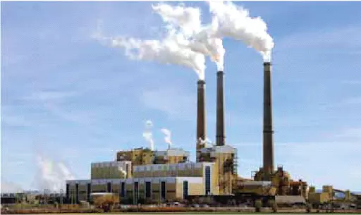
    • Thermal Power Plant
    • Steel & Foundries
    • Cement production plant
    • Chemical & Fertilizer production process plant, many more..

    Why is Flue Gas Flow Measurement so important?

    As most flue gases emission contains air pollutants that are harmful to human health. So continuous emission monitoring systems (CEMS) are mandatory for providing reporting to state & central pollution control boards for environmental pollution control. It is important to measure the composition and concentration of polluting gases as well as mass flow rates to arrive at the total emission discharge in the environment.

    Flue gas flow rate measurement is imperative for below reasons

    • Optimizing ESP performance by maintaining design parameters such as specific collection area, gas velocity, and treatment time within ESP in control.
    • Indicates early warning for Preheater condenser failures
    • Help regulates harmful pollutants, dust emission controls
    • Useful information on optimizing mass balance
    • Simple design to operate Helps in energy conservation easily
    • Predictive & preventive measures for optimizing their process efficiency and reducing harmful emissions in the environment.

    Process conditions of Flue gas in Stack

    Process engineers design the lowest possible heat loss into the environment for better thermal efficiency of the power plant. Flue gas process conditions with optimum design have typically as below process parameters:

    • Composition: Flue gas with moderate dust/fly-ash particle (Coal-fired).
    • Process temperature: 130⁰C to 180⁰C
    • Process velocity : recommended approx.12m/s to 20m/s.

    Where to monitor Flue Gas Flow Rate?

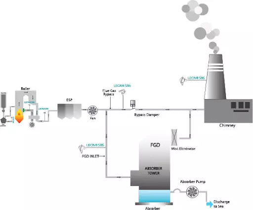
    To get the optimum efficiency it can be a monitor at :

    • Chimney or Stack near to the point of sampling for lab analysis.
    • Inlet of Flue gas desulfurization plant (Wet FGD / Dry FGD ) in Thermal Power plant
    • Process stack in chemical production, fertilizer, steel plants
    • Process venting systems

    Flue gas flow meter monitoring

    Which are the main technologies available for Flue Gas Flow Monitoring?

    Process instrumentation engineer’s task is to identify which of the above will be the best suitable technology.

    Factors to consider while selecting a flowmeter

    Below are some important factors to be considered & evaluated with comparing technologies for optimum selections:

    • Duct or Pipe Dimension
    • Insulation thickness, if any.
    • Process conditions such as flow rate, pressure, temperature, density, viscosity, dirt & moisture, etc.
    • Installation conditions such as horizontal, vertical & available straight lengths, time & effort, etc.
    • Accuracy & repeatability needed
    • Process turndown ratio needed
    • Budgeted price

    Based on the above factors process engineer has to understand the working principle, PROS, and CONS  of different flow measurement technology & its possibility for selection as mentioned below:

    1. DIFFERENTIAL PRESSURE BASED FLOW METER (AEROFOIL/ ANNULAR/ PITOT-TUBE)

    Working Principle 

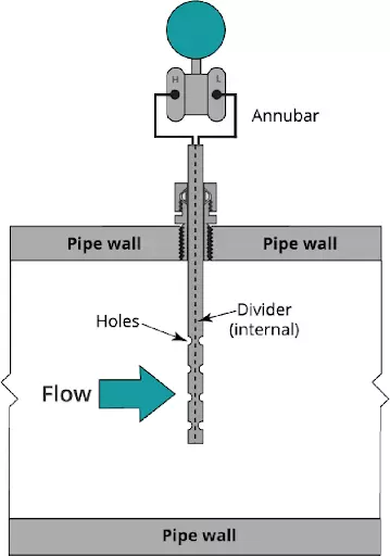
    Aerofoil /Annubar / Pitot-Tube works on the principle of measuring differential pressure measurement by creating restriction in the path of flow and measures differential pressure across primary flow elements and derives volumetric flow rate. With additional continuous pressure and temperature (instantaneous density) compensation mass flow rate can be derived.

    PROS

    • Established Standard BS-1042/ISO 5167 for Volumetric flow measurement
    • Suitable up to 5mtrs or higher
    • Rugged designed for any process conditions of industries
    • Any orientation possible
    • Highly Repeatable
    • Site calibration easy

    CONS

    • Higher pressure drop
    • Needs periodic maintenance
    • Lower Accuracy 3% FSD & may drift time to time
    • Lower turn-down ratio 4:1
    • Lower flow sensitivity
    • Susceptible to clogging
    • High wear factor
    • High Installation cost

    2. NON-CONTACT ULTRASONIC FLOWMETER 

    Working Principle

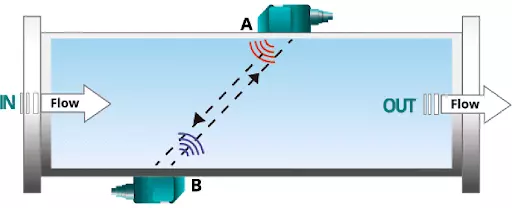
    It measures the volumetric flow rate consisting of a pair of ultrasonic trans-receiver that transmits and receives ultrasonic pulses across the flue gas path in both directions, resulting in transit time (time difference) is proportional to stack gas velocity. It depends mainly on the sound velocity of the gas.

    PROS

    • Derives volumetric flow rate by ultrasonic beam transit-time measurement
    • Used for Pipe diameter up to 10 meters
    • Suitable for temperature up to max 450⁰C
    • Horizontal or vertical orientation is possible
    • Turn down ratio better than 100:1

    CONS

    • Gas must be dry and clean
    • Accuracy up to ±1.5%-3% RD & repeatability ±1%
    • High Initial Cost
    • Installation need good technical knowledge
    • Not suitable for pipes with inner lining
    • Drift due to change in flue-gas sound velocity
    • Technical knowledge for installation must

    3. INSERTION OF THERMAL MASS FLOWMETERS 

    Working Principle

    Thermal mass flowmeters work on the physical principle of thermal dispersion from a heated element to the ambient medium (eg. air or gases). This is affected by the velocity, density (temperature and pressure), and by the characteristic of the medium. The amount of needed energy is a function of the temperature difference ∆T and the mass flow.

    Flue gas flows through two RTD Pt-100 one reference (Tref) and the other Heater (Th). The temperature difference (over-temperature) ∆t between the reference sensor (medium temperature) and the heater sensor is controlled constantly. As per King’s Law, the higher the mass flow rate, the higher the cooling effect of the heater sensor, thus higher the power required to maintain the differential temperature constant. Therefore the heater power is proportional to the gas mass flow rate.

    PROS

    • Works on constant calorimetric temperature anemometry (Thermal dispersion)
    • Pipe sizes suitable 15mm to 10 meters
    • Insertion is rugged and works up to 400⁰C & 16bar or more
    • Any orientation possible
    • Better accuracy < ±2%RD of mass flow rate
    • Highest turndown ratio 100:1 or better
    • Adjustable & versatile
    • Lowest pressure drop
    • Low cost of ownership against other flow technology
    • Online thermal conductivity compensation

    CONS

    • Mechanically vulnerable to damage
    • Flow straightener recommended
    • Affected by high moisture (>10%Vol.) & dirt/dust needs periodic cleaning or purging system

    NOTE: Above article don’t claim accuracy and it is for general pros and cons guidance on flow technologies as per practical experience there may be improvements or different configuration possible from different manufacturers which may eliminate some disadvantages.

    CONCLUSION

    Considering the above advantages and disadvantages & process conditions with respect to different flowmeter technologies for the flue gas flow measurement process engineers can decide on suitable flowmeters for optimum performance.

    Insertion thermal mass flowmeters are a preferable choice for stack diameter up to 8 meters or less with moderate wet or dust load conditions with a suitable purging system can be a good & cheaper alternative against DP Type flow meter.

    Ultrasonic gas flow meters can be a good alternative for large stack diameters above 8 meters against DP  & Thermal Mass Flowmeters.

    Request to kindly write us your inquiry related to the above application and will happy to assist with flow solutions at our best.

  • Step by step guide for Gas Flow Meter Calibration

    Step by step guide for Gas Flow Meter Calibration


    A gas flowmeter is used to monitor the volumetric or mass flow rate of various process gases in industrial plants and machinery. The flow rate refers to the speed at which fluid is moving through closed pipes or ducts at a given time. Modern instrumentation & control engineering design needs monitoring of fluid flow rates to optimize the use of gases and improve the efficiency of processes and equipment. Therefore, a gas flow meter device must be calibrated against a reference or a master calibration system.

    Due to process & environmental conditions flow meters may have some drift in flowrate readings which needs recalibration periodically for the flow range it is designed for, to achieve the desired accuracy for smooth process operation. Some organizations have an ISO audit system in place which needs recalibration at a specific time frame.

    Types of gas flowmeter available in market

    Various flowmeter technologies are available currently in the market which needs to be calibrated and there are different methods for calibration based on product design.

    and there are different methods for calibration based on product design.

    Types of calibration procedures? 

    Gas flowmeter calibration systems mainly depend on product technology to be calibrated. Some widely used calibration procedure is as below:

    •  Reference Master Meter calibration
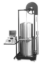
    • Primary Air by Bell / Piston prover calibration
    • Critical Flow Venturi (Sonic nozzle) calibration
    • Wind Tunnel Air Velocity calibration
    • Onsite validation by calibrated reference gas flowmeter

    Gas flow meter calibration is done as per above various calibration systems which involve comparison and adjustment of the flowmeter under test confirming to National & International standards mainly following ISO 17025 standards for calibration methods.

    Reference Master Meter Calibration Procedures

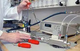
    Reference Master meter calibration compares with duly calibrated master gas flowmeter traceable to national accredited calibration laboratories with a gas flowmeter under test at desired flow ranges and adjusts its calibration as per desired accuracy tolerances.

    Reference Master meter calibration steps :

    • Place the reference master meter in series with the flow meter under test.
    • Compare the readings of the master flow meter and flow meter using air or standard gas flow rate with a close loop calibrated volumetric tank storage system.
    • Calibrate the flowmeter under test to conform with the master flow meter calibration.

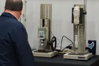
    Piston / Bell Prover Gravimetric Calibration Procedures

    airflow meter in india leomi
    bell Prover gravimetric
    Piston-Gravimetric-Calibration leomi
    Gravimetric calibration air flow meter

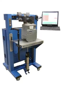
    Gravimetric calibration is one of the most accurate and cost-effective volumetric and gas mass flow meter calibration procedures at low pressure. Piston prover-based gravimetric method is ideal for gases for low flow rates whereas Bell Prover calibration is mainly used for a high flow rate of air calibration. The calibration flow laboratory is always maintained at controlled ambient conditions such as temperature, humidity for master flow meters’ best performance.

    In the piston or bell prover flow meter calibration procedure, a known volume of fluid is forced through a flow meter under test. The piston /bell prover is a cylindrical device with known internal diameter. The piston/bell prover contains a piston/ bell which produces volumetric flow by positive displacement. The piston prover method is ideal for Low flow rate gas or liquid thermal mass flow controller, ultrasonic flow meter & turbine flow meter calibration to a high degree of accuracy.

    Piston / Bell prover Gravimetric calibration steps:
    • Fix the flowmeter in a series of piston/bell prover systems for calibration.
    • Desired gas flow via test flowmeter enters in the piston/bell prover which will move piston/bell upwards with detecting distance between sensors for known volume between is measured.
    • Measuring travel time, pressure, temperature, and flow rate at reference conditions is calculated via software systems.
    • Compare the calculated flow rate with the flowmeter under test and adjust it to the measured flow rate.

    airflow meter calibration

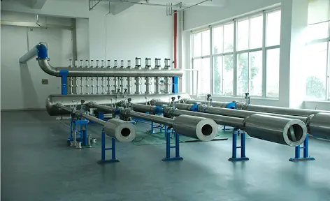
    Critical Flow Venturi ( Sonic Nozzle ) Calibration Procedures

    Critical Flow Venturi Nozzle (Sonic Nozzles) is used for different flow rate capacities designed as per ISO 9300:2015 as a reference standard. Sonic nozzles are considered the best reference standard for calibration of precision flow meters used for custody transfer. Gas flow accelerates to the critical velocity at the throat (known as sonic velocity) where it will reach a steady flow state of single-phase gases. This sonic velocity is a specific point velocity at a certain pressure which is accurate as a reference velocity for calibrating a flowmeter under test. It is used for almost all fixed type flowmeters mainly vortex flowmeter, turbine flowmeter, thermal mass flowmeter, Coriolis flowmeter, etc.

    Sonic nozzle calibration steps:
    • Fix the flowmeter in series of the pipeline where calibrated sonic nozzle
    • Start air compressor in the testing system
    • When sonic velocity reaches the measuring section, the flowmeter under calibration needs to adjust its reading & set it. Repeat the same steps for different sonic velocity points for a specific flow rate.

    Comparing flow rate from a sonic nozzle with flow meter under calibration.

    manufatuerer of air flow meter in india

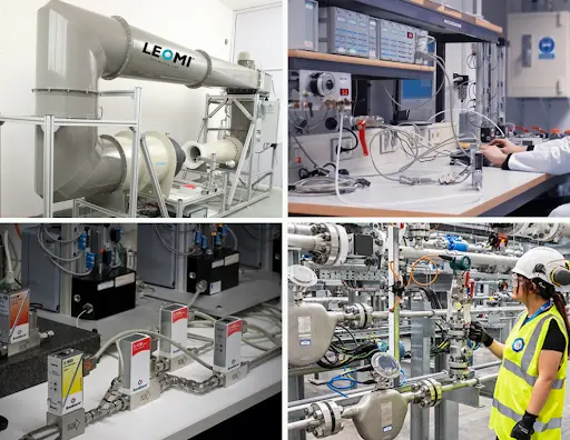
    Wind Tunnel Calibration Procedures

    The wind tunnel is designed for the characterization of air velocity, air turbulence for various different turbomachinery and instruments calibration and simulation. There are different proprietary & standard designs of wind tunnels installed. It has an open test chamber for calibration or test of the device under test. It is widely used for various types of flow sensor calibration such as hot-wire/vane anemometer, insertion thermal mass flowmeter, pitot tube, measuring probes, etc.

    Wind tunnel calibration steps:

    • Install a flow sensor probe in the test chamber with desired insertion depth and correct orientation.
    • Step by step increasing reference velocity and measure & record flow sensor under test.
    • Based on reference velocity, plot a curve and suitable interpolation & extrapolation flow calculations upload curve into a device under test.

    calorimetric flow meter in india
    thermal mass flow meter in india

    Onsite validation & calibration procedures

    Onsite validation and calibration of gas flowmeters are also possible in some industrial applications. This method is not accurate as the above methods but can validate gas flowmeters in use having high errors or non-repeatability.

    Mainly two ways are possible for onsite validation:

    • Pump-up test with pressure vessel
    • With calibrated reference gas flowmeter to be installed in series

    Pump-up test steps:

    • The pressure vessel in series of gas flowmeter
    • Start Gas flow and note gas flow meter reading and timer for filling a pressure vessel
    • Pressure vessel pressure with respect to volume capacity and gas flow meter totalizer to be compared
    • Validation is done by comparing both results and errors.

    Calibrated reference gas flowmeter:

    • Install calibrated reference gas flowmeter in series of gas flowmeter under validation
    • Compare both flowmeter result and compute the error

    For any technical queries, we would be pleased to provide you related information.