Author: admin

  • Compressed air flow measurement in textile industry

    Compressed air flow measurement in textile industry

    compressed-air-flowmeter-in-textile-industries 1 (1)

    Compressed air flow measurement in textile industry

    Air compressed gas is one among the essential requirements of the textile industry, with the rise in modernization and automation the utilization of compressed gas is increasing rapidly. compressed gas is employed in most of the method machines from blow rooms, carding, spinning, winding, weaving, and other machineries for both controlling and operations.

    Only 20-30% of #energy reaches the purpose of end-use and balance 70-80% of the energy of the facility of the first cause being converted to unusable heat and other system losses.

    With Leomi 586 Thermal Mass Flowmeter you can measure the flow and optimize the same.

  • PROVIDING FLOW METER TECHNOLOGY WITH IN-HOUSE CALIBRATION

    PROVIDING FLOW METER TECHNOLOGY WITH IN-HOUSE CALIBRATION

    The global flow meter manufacturing industry grew to $8.9 billion in 2020, and it is projected to grow at a CAGR of 5.70 percent till FY2028. The market in India is also expected to see considerable growth due to developments in process automation in various industry core sectors such as Power, water management, chemicals, steel & cement, and more. The global flow meter manufacturing industry grew to $8.9 billion in 2020, and it is projected to grow at a CAGR of 5.70 percent till FY2028.

    The market in India is also expected to see considerable growth due to developments in process automation in various industry core sectors such as Power, water management, chemicals, steel & cement, and more.The global flow meter manufacturing industry grew to $8.9 billion in 2020, and it is projected to grow at a CAGR of 5.70 percent till FY2028. The market in India is also expected to see considerable growth due to developments in process automation in various industry core sectors such as Power, water management, chemicals, steel & cement, and more.

    However, the flow meter industry demands fine-tuning of its process& factory automation which requires products with high accuracy along with a reasonable price range. Manish S. Patel, Director, LEOMI, says, “The primary factor that sets our company apart from the rest of the players in the High-quality Thermal mass flow meter engineered in In­dia for process air and gas flow measurement with various customization options. It is made with German technolo­gy by transfer from softflow.de and has a robust design with a proven track record globally for more than 20 years. We have installed India’s first fully automatic In-house calibration facility & in-house electronic development which provides quick service support to the customers with an affordable pricing range”.


    flow meter manufacturers

    CUSTOMIZED & ENGINEERED PRODUCTS

    Manish adds, “There are large requirements of quality in­ instrumentation with high accuracy and reliability which are currently not available in India forcing the companies to im­port from other countries. Our priority at Leomi is the development of our products into an application based on the expectations of the core sector Industries that we serve, such as power plants and steel & cement as both these industries require customized and engineered products with high accuracy and reliability for their operations. We ensure the quality of our products by meeting all the international standards which are crucial for a product of this type and also helps in exceeding client expectations on performance and reliability”.

    LEOMI started the commissioning of its project along with the establishment of its manufacturing facilities in 2019. It had also recorded a substantial amount of growth in the nuclear, thermal power, steel & textile sector Manish high­ lights, “There is still a lot of room for growth in the Thermal Power sector for flue gas flow measurement and also in the corrosive process gas emissions. We have also exported to Germany, Vietnam, Nigeria to name a few for compressed air and gas” LEOMI is also a registered Start-up India company having an ISO 9001:2015 certification which is a testament to their excellence.

    APPLICATION-ORIENTED PRODUCTS

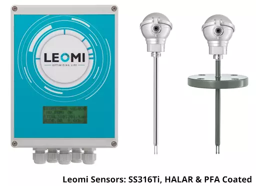
    LEOMI offers flow meter products that have different types of sensor construction such as stainless steel, Hastelloy C276, HALAR & PFA coatings for a wide range of applications in various industries. The Insertion type of flow meters can be used in an adjustable and versatile manner which is used to monitor multiple locations with a wide temperature range up to 400°C. LEOMI also provides inline flow meters for permanent installation for systemic inspection.

    Manish emphasizes, “Currently our company is working on projects in the power sector which includes the nuclear en­ energy, thermal power generation and for the municipal corpo­ration sewage treatment plant in the aeration air, landfill gas monitoring in the solid waste management process, biogas monitoring process in the food and starch industry.

    LEOMI has developed a perfect tool for compressed air monitoring & recording for energy auditors for conservation initiatives with Thermal mass flowmeter”.

    AIMING FOR OPTIMIZATION

    Manish concludes, “The tagline of our company is ‘Opti­mizing Life’ as a central idea for developing products and solutions which help in optimization of process and equip­ment. Optimization helps in energy conservation in various process industries.

    The company also works on developing import substitute technology products which will support the India program for becoming ATMANIRBHAR (self-re­ learned) by reducing the dependency of importing reliable equipment from other countries”.

  • EMERGING FLOW MEASUREMENT SOLUTIONS FOR AIR AND GAS APPLICATIONS FROM LEOMI INSTRUMENTS

    EMERGING FLOW MEASUREMENT SOLUTIONS FOR AIR AND GAS APPLICATIONS FROM LEOMI INSTRUMENTS

    air flow meter in India

    Current market conditions demand superior and reliable products that are competitively priced. This implies industries improve the overall efficiency of equipment & plant processes and simultaneously conserve energy for achieving desired results. Flow measurement is becoming crucial for conserving energy for various utility measurements such as water, compressed air, natural gas, etc. Flow measurement is also important for various other process gases for emission controls. With strict emission norms, process efficiency needs to be tightly controlled where flow measurement is the ultimate requirement.

    LEOMI An ISO-9001:2015 certified & Start-up India recognized company.

    Leomi aiming for “Optimizing Life” has identified various industrial applications helping in overall process optimization and energy conservation by manufacturing high quality and reliable Thermal mass flow meters with a technical collaboration with Softflow.de which has more than 20 years of proven experience in this field. Leomi has also installed India’s first fully automatic wind tunnel for In-house calibration of Insertion thermal mass flowmeter and various velocity-based instruments.

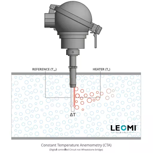
    Leomi Insertion thermal mass flow meter design is based on Constant Temperature Anemometry combined with digital precision over temperature control. The physical principle of thermal dispersion from a heated element to the ambient medium (example: air or gases). This is affected by the velocity, density (temperature and pressure), and by the characteristic of the medium. The amount of needed energy is a function of the temperature difference ∆T and the mass flow.

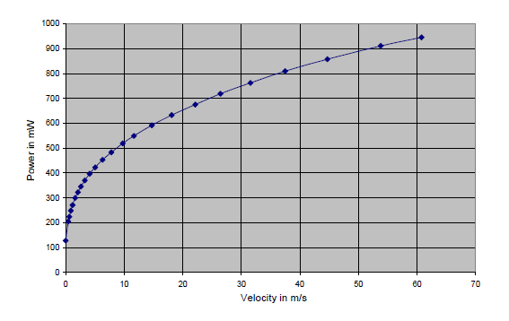
    Gas flowing through two RTD Pt-100 one reference (Tref) and the other Heater (Th). The temperature difference (over-temperature) ∆t between the reference sensor (medium temperature) and the heater sensor is controlled constantly. As per King’s Law, the higher the mass flow rate, the higher the cooling effect of the heater sensor, thus higher the power required to maintain the differential temperature constant. Therefore, the heater power is proportional to the gas mass flow rate. (As per figure shown)

    Leomi-compressed-air-flow-meter.

    Leomi Thermal mass flow meter offer benefits such as:

    • No moving parts, robust metallic construction, and direct mass flow measurement of gases
    • No pressure drop which saves energy against other conventional flowmeters
    • The highest turn down-ratio better than 100:1 provides high sensitivity helps in leak detection
    • High accuracy <±1.5% and resolution against conventional flow meters.
    • Designed up to 400⁰C operating temperature and pressure up to 16bar or higher.
    • Easily cleanable sensor & No significant effect of moisture like thin-film sensor does.
    • Can work in dirty or wet gas environments with accessories
    • Adjustable in various pipe sizes and versatile for different gas and mixtures.
    • Digital controlled with No drift and long term mechanically stable design

    Applications where Leomi product innovations have been successfully used:

    • Compressed air flow, pressure, dew-point, power monitoring & logging for energy audits, which provides complete compressor’s data with overall efficiency and able to identify leakages and conserve energy.
    • Flue gas & combustion air flow measurement for stack gas for emission controls having various features to the suits power plant and industrial furnaces needs
    • Aeration basin airflow & dissolved oxygen control system in the wastewater treatment plant
    • Natural gas overall utility monitoring solution in one instrument
    • Biogas flow measurement solutions for food and beverages.
    • Chemical process gas emission by special HALAR® coated, PFA coated construction flow sensor for highly corrosive gases
    • Welding utility gas & medical gas flow monitoring and recording for consumption & cost control.
    • Ventilation air control systems for critical power plants rooms and pharma clean rooms

    Leomi has also supplied Insertion thermal mass flowmeter to various flue gas applications such as:

    • Stack gas flow measurement in few of the India’s renowned coal based thermal power plant manufacturers
    • Wet HCL stack gas flow measurement at renowned chemical manufacturers producing Hydrochloric 30% conc.
    • HCl and SO2 (equimolar) with roughly 1% moisture gas flow process exhaust from fine chemical manufacturers

    LEOMI’s technical team is continuously working on research of other alternatives for various gas mass flow measurements solutions keeping in mind different industries’ process conditions.

    Request to kindly write us your inquiry related to the above application and will happy to assist with flow solutions at our best. For more information, log on to https//www.leomi.in & follow us on our LinkedIn page for more updates.

  • PROS & CONS OF DIFFERENT GAS FLOW MEASUREMENT TECHNOLOGIES

    PROS & CONS OF DIFFERENT GAS FLOW MEASUREMENT TECHNOLOGIES

    compressed air flow meter

    This blog will try to highlight the pros and cons of different gas flow measurement technologies available in the market which will help process instrumentation engineers to effectively choose the best flow metering technology for defined application which results in optimum results w.r.t cost versus performance ratio.

    Below are the Gas flow measurement technologies available :

    1. DIFFERENTIAL PRESSURE-BASED ORIFICE/AVERAGING PITOT TUBE/VENTURI/AEROFOIL
    2. THERMAL MASS–INSERTION TYPE
    3. CORIOLIS
    4. VORTEX
    5. TURBINE
    6. ULTRASONIC – CLAMP-ON TYPE

    The process instrumentation engineer’s task is to identify which of the above will be the best suitable technology.

    Below are some important factors to be considered & evaluated with comparing technologies for optimum selections:
    • Pipe sizes
    • Process conditions such as flow rate, pressure, temperature, density, viscosity, dirt & moisture, etc.
    • Installation conditions such as horizontal, vertical, or inclined & available straight lengths, time & efforts, etc.
    • Accuracy & repeatability needed
    • Process turndown ratio needed
    • Budgeted price

    Based on the above factors we will try to summarize the PROS and CONS of different flow technologies & its a possibility for selection. However, the ultimate choice is of the process engineer who has some specific technologies dominance and/or experience.

    1. DIFFERENTIAL PRESSURE-BASED FLOW METER (ORIFICE / AEROFOIL / VENTURI / PITOT  TUBE)

    PROS

    • Established Standard BS-1042/ISO5167 for Volumetric flow measurement
    • Suitable for 15mm to 10mtrs or higher  pipe sizes
    • Rugged designed for any process conditions of industries
    • Any orientation possible
    • Highly Repeatable
    • Low budget upto 300mm pipe size
    • Site calibration easy

    CONS

    • Higher pressure drop
    • Needs periodic maintenance
    • Lower Accuracy 3% FSD & may drift time to time
    • Lower turn-down ratio 4:1
    •  Lower flow sensitivity
    • Susceptible to clogging
    • High wear factor

    2. THERMAL MASS FLOW METER – INSERTION TYPE

    PROS

    • Works on constant temperature anemometry (thermal dispersion)
    • Pipe sizes suitable 15mm to 10000mm
    • Insertion is rugged and works up to 400⁰C & 16bar or more
    • Any orientation possible
    • Better accuracy ±2%RD
    • Highest turndown ratio 100:1 or better
    • Insertion type is adjustable & versatile
    • Insertion has a lowest pressure drop
    • The low initial cost above 100mm pipe sizes

    CONS

    • Mechanically vulnerable to damage
    • Susceptible to turbulence & vibrations
    • Flow straightener recommended
    • Affected by high moisture (>10%Vol.) & dirt/dust needs periodic cleaning or purging system

    3. CORIOLIS FLOWMETER

    PROS

    • Works on Coriolis effect by oscillating tube provides direct mass flow rate
    • Suitable from 2mm to 300mm pipe sizes
    • Suitable for high pressure upto 400bar or more
    • Any orientation possible
    • Highest accuracy (±0.1%- ±0.5%RD) & Repeatability (±0.02%)
    • Highest turn down ratio 100:1 or more

    CONS

    • High-pressure drop
    • Not suitable larger pipe dia than 300mm
    • Not suitable for higher temperatures above 120⁰C
    •  Sensitive to vibrations
    • High Initial Cost

    4. VORTEX FLOWMETER

    PROS

    • Derives volumetric flowrate by vortices frequency measurement principle
    • Suitable from 15mm to 300mm
    • Horizontal or vertical orientation is possible
    • Suitable up to 300⁰C temperature & pressure up to 40bar
    • Better accuracy up to (±1.5%RD) & Repeatability (±0.02%)
    • Low Initial cost up to 80mm size

    CONS

    • Higher pressure drop
    • Lower turn-down ratio 10:1
    • Installation needs utmost care
    • Susceptible to vibrations & turbulence
    • Needs periodic maintenance
    • High Initial cost 100mm & above size

    5. TURBINE FLOWMETER

    PROS

    • Derives volumetric flowrate by moving the rotating turbine frequency
    • Pipe sizes suitable: 6mm to 300mm
    • Suitable for high pressure 250 bar & temperature up to 200⁰C
    • Horizontal or vertical orientation is possible
    • High accuracy up to ±1% RD & repeatability ±0.25%
    • Low initial cost

    CONS

    • Gas must be dry and clean
    • Susceptible to vibrations & turbulence
    • Moving parts needs periodic maintenance
    • High wear factor

    6. ULTRASONIC FLOWMETER – CLAMP-ON TYPE

    PROS

    • Derives volumetric flowrate by ultrasonic beam transit-time measurement – Non-Intrusive &  Fixed Type
    • Pipe sizes suitable : 10mm to 1600mm
    • Suitable for high pressure 200 bar & temperature upto max 200⁰C
    • Horizontal or vertical orientation possible
    • Better accuracy upto ±1%-3% RD & repeatability ±0.25%
    • Turn down ratio better than 100:1
    • Low Installation cost

    CONS

    • Gas must be dry and clean
    • High Initial Cost
    • Installation need good technical knowledge
    •  Not suitable for pipes with inner lining
    *NOTE: Above article don’t claim accuracy and it is for general guidance on flow technologies as per practical experience there may be improvements or different configuration possible from different manufacturers which may eliminate some disadvantages.

    Considering the above Pros & Cons of different flow measurement principle user can be able to understand its need and compare basic important parameters which will ensure optimum selections. Hope this will help in your future decisions. Pls.do write us a comment on the same.

    LEOMI, A make-in-India start-up registered company manufacturing Insertion Thermal mass flowmeter which has many inherent advantages in terms of performance versus cost ratio.

  • ADVANCEMENT IN FLUE GAS FLOW MONITORING

    ADVANCEMENT IN FLUE GAS FLOW MONITORING


    The efficient operation of today’s power plant depends largely upon accurate & repeatable measurement of primary and secondary airflow to coal mills, flue gas recirculation flow, overfire air flow, airflow to individual burners, etc.

    Flue gas or Stack gas emission flow rate measurement is nowadays important for quantifying emission (CEMS) for environmental reporting for Govt. Authorities for pollution control. Flue gas flow measurement are gases emitted due to the combustion process due to heating of fuel (liquid or solid or gaseous) & Air with a stoichiometric ratio in:

    • Boiler Heating
    • Process furnaces

    Flue gas production due to combustion mainly consists of

    • Nitrogen (N2)
    • Carbon monoxide (CO)
    • Carbon dioxide (CO2)
    • Traces of Sulphur dioxide (SO2),
    • Nitrogen oxides (NO, NO2)
    • Particulate matters (SPM)
    • Moisture

    Flue Gases are gases emitted due to combustion process due to heating of fuel (liquid or solid or gaseous) & Air in:

    • Thermal Power Plant
    • Steel & Foundries
    • Cement production plant
    • Chemical & Fertilizer production process plant, many more..

    Why is Flue Gas Flow Measurement so important?

    As most flue gases emission contains air pollutants that are harmful to human health. So continuous emission monitoring systems (CEMS) are mandatory for providing reporting to state & central pollution control boards for environmental pollution control. It is important to measure the composition and concentration of polluting gases as well as mass flow rates to arrive at the total emission discharge in the environment.

    Flue gas flow rate measurement is imperative for below reasons

    • Optimizing ESP performance by maintaining design parameters such as specific collection area, gas velocity, and treatment time within ESP in control.
    • Indicates early warning for Preheater condenser failures
    • Help regulates harmful pollutants, dust emission controls
    • Useful information on optimizing mass balance
    • Simple design to operate Helps in energy conservation easily
    • Predictive & preventive measures for optimizing their process efficiency and reducing harmful emissions in the environment.

    Process conditions of Flue gas in Stack

    Process engineers design the lowest possible heat loss into the environment for better thermal efficiency of the power plant. Flue gas process conditions with optimum design have typically as below process parameters:

    • Composition: Flue gas with moderate dust/fly-ash particle (Coal-fired).
    • Process temperature: 130⁰C to 180⁰C
    • Process velocity : recommended approx.12m/s to 20m/s.

    Where to monitor Flue Gas Flow Rate?

    To get the optimum efficiency it can be a monitor at :

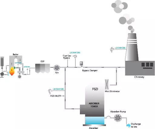
    • Chimney or Stack near to the point of sampling for lab analysis.
    • Inlet of Flue gas desulfurization plant (Wet FGD / Dry FGD ) in Thermal Power plant
    • Process stack in chemical production, fertilizer, steel plants
    • Process venting systems

    Flue gas flow meter monitoring

    Which are the main technologies available for Flue Gas Flow Monitoring?

    Process instrumentation engineer’s task is to identify which of the above will be the best suitable technology.

    Factors to consider while selecting a flowmeter

    Below are some important factors to be considered & evaluated with comparing technologies for optimum selections:

    • Duct or Pipe Dimension
    • Insulation thickness, if any.
    • Process conditions such as flow rate, pressure, temperature, density, viscosity, dirt & moisture, etc.
    • Installation conditions such as horizontal, vertical & available straight lengths, time & effort, etc.
    • Accuracy & repeatability needed
    • Process turndown ratio needed
    • Budgeted price

    Based on the above factors process engineer has to understand the working principle, PROS, and CONS  of different flow measurement technology & its possibility for selection as mentioned below:

    1. DIFFERENTIAL PRESSURE BASED FLOW METER (AEROFOIL/ ANNULAR/ PITOT-TUBE)

    Working Principle 

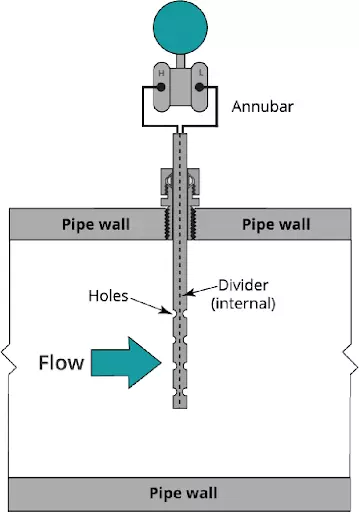
    Aerofoil /Annubar / Pitot-Tube works on the principle of measuring differential pressure measurement by creating restriction in the path of flow and measures differential pressure across primary flow elements and derives volumetric flow rate. With additional continuous pressure and temperature (instantaneous density) compensation mass flow rate can be derived.
    PROS

    • Established Standard BS-1042/ISO 5167 for Volumetric flow measurement
    • Suitable up to 5mtrs or higher
    • Rugged designed for any process conditions of industries
    • Any orientation possible
    • Highly Repeatable
    • Site calibration easy

    CONS

    • Higher pressure drop
    • Needs periodic maintenance
    • Lower Accuracy 3% FSD & may drift time to time
    • Lower turn-down ratio 4:1
    • Lower flow sensitivity
    • Susceptible to clogging
    • High wear factor
    • High Installation cost

    2. NON-CONTACT ULTRASONIC FLOWMETER 

    Working Principle

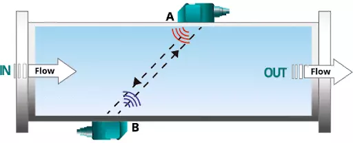
    It measures the volumetric flow rate consisting of a pair of ultrasonic trans-receiver that transmits and receives ultrasonic pulses across the flue gas path in both directions, resulting in transit time (time difference) is proportional to stack gas velocity. It depends mainly on the sound velocity of the gas.
    PROS

    • Derives volumetric flow rate by ultrasonic beam transit-time measurement
    • Used for Pipe diameter up to 10 meters
    • Suitable for temperature up to max 450⁰C
    • Horizontal or vertical orientation is possible
    • Turn down ratio better than 100:1

    CONS

    • Gas must be dry and clean
    • Accuracy up to ±1.5%-3% RD & repeatability ±1%
    • High Initial Cost
    • Installation need good technical knowledge
    • Not suitable for pipes with inner lining
    • Drift due to change in flue-gas sound velocity
    • Technical knowledge for installation must

    3. INSERTION OF THERMAL MASS FLOWMETERS 

    Working Principle

    Thermal mass flowmeters work on the physical principle of thermal dispersion from a heated element to the ambient medium (eg. air or gases). This is affected by the velocity, density (temperature and pressure), and by the characteristic of the medium. The amount of needed energy is a function of the temperature difference ∆T and the mass flow.

    Flue gas flows through two RTD Pt-100 one reference (Tref) and the other Heater (Th). The temperature difference (over-temperature) ∆t between the reference sensor (medium temperature) and the heater sensor is controlled constantly. As per King’s Law, the higher the mass flow rate, the higher the cooling effect of the heater sensor, thus higher the power required to maintain the differential temperature constant. Therefore the heater power is proportional to the gas mass flow rate.

    PROS

    • Works on constant calorimetric temperature anemometry (Thermal dispersion)
    • Pipe sizes suitable 15mm to 10 meters
    • Insertion is rugged and works up to 400⁰C & 16bar or more
    • Any orientation possible
    • Better accuracy < ±2%RD of mass flow rate
    • Highest turndown ratio 100:1 or better
    • Adjustable & versatile
    • Lowest pressure drop
    • Low cost of ownership against other flow technology
    • Online thermal conductivity compensation

    CONS

    • Mechanically vulnerable to damage
    • Flow straightener recommended
    • Affected by high moisture (>10%Vol.) & dirt/dust needs periodic cleaning or purging system

    NOTE: Above article don’t claim accuracy and it is for general pros and cons guidance on flow technologies as per practical experience there may be improvements or different configuration possible from different manufacturers which may eliminate some disadvantages.

    CONCLUSION

    Considering the above advantages and disadvantages & process conditions with respect to different flowmeter technologies for the flue gas flow measurement process engineers can decide on suitable flowmeters for optimum performance.

    Insertion thermal mass flowmeters are a preferable choice for stack diameter up to 8 meters or less with moderate wet or dust load conditions with a suitable purging system can be a good & cheaper alternative against DP Type flow meter.

    Ultrasonic gas flow meters can be a good alternative for large stack diameters above 8 meters against DP  & Thermal Mass Flowmeters.

    Request to kindly write us your inquiry related to the above application and will happy to assist with flow solutions at our best.

  • WEBINAR ON Optimizing Waste Water Aeration System – Challenges and Solutions

    WEBINAR ON Optimizing Waste Water Aeration System – Challenges and Solutions

    Presenter:


    Manish Patel
    Manish S Patel

    Mr. Manish Patel is a Mechanical Engineer by qualification and a First generation entrepreneur. He started from scratch & developed a considerable business establishment with consistent efforts in course of years acquired skills such as Sales & Marketing, Brand management, Business development strategy & risk analysis. 

    He has an in-depth subject knowledge in Flow measurementPassionate about discovering inner self & believe in “Karma-yoga” as a path for liberation from negative energies of mind, intellect, consciousness & ego and remain in a constant blissful state. “Blessed be ever and everywhere” is the mantra of his life.


    Optimizing Waste Water Aeration System – Challenges and Solutions


    Wastewater aeration is a process that occurs when air is added directly to wastewater, which allows for aerobic biodegradation of any pollutants contained within. Aeration is an essential component of treating wastewater.

    Aeration wastewater treatment accounts for approximately 60% of the total energy consumption in wastewater treatment plants. Energy consumption is the main cost driver in wastewater treatment, and its optimization is one of the many challenges faced by plant operators also having to meet ever more demanding safety legislation.

    While there are many challenges facing wastewater treatment plants the biggest concern is the impact the wastewater will have on the ecosystems of the world. 

    However, Wastewater treatment could be challenging at times and require technology matching to suit the application.

    This webinar session will aim at targeting Optimizing Waste Water Aeration System and its various Challenges and will be followed by best practices to overcome those challenges.

  • WEBINAR ON Compressed Air Flow Measurement Challenges And Solutions

    WEBINAR ON Compressed Air Flow Measurement Challenges And Solutions

    Presenter:


    Manish Patel
    Manish S Patel

    Mr. Manish Patel is a Mechanical Engineer by qualification and a First generation entrepreneur. He started from scratch & developed a considerable business establishment with consistent efforts in course of years acquired skills such as Sales & Marketing, Brand management, Business development strategy & risk analysis.

    He has an in-depth subject knowledge in Flow measurementPassionate about discovering inner self & believe in “Karma-yoga” as a path for liberation from negative energies of mind, intellect, consciousness & ego and remain in a constant blissful state. “Blessed be ever and everywhere” is the mantra of his life.

    Compressed Air Flow Measurement Challenges And Solutions

    In most facilities, compressed air usage typically varies widely throughout the day, from very heavy at times of peak manufacturing to small flows (perhaps due to leakage) when most production is on standby. With more accurate compressed air flow measurement, companies are putting a price tag on compressed air and making educated choices that lead to cost savings.

    Compressed air generally uses more electricity than any other type of equipment, and accounts for as much as a third of the energy usage in an industrial facility.  Insertion Style Thermal Mass Flow Meters help measure the airflow and identify leaks in compressor systems, track overall usage to improve plant efficiency and help reduce consumption. This can save thousands of dollars each month in large industrial applications.

    However, flow measurement of compressed air could be challenging at times and require technology matching to suit the application.

    This session will aim at targeting compressed air flow measurement challenges and will be followed by best practices to overcome those challenges.

    This webinar gives you the opportunity to Learn about Optimizing Your Air System.

    Download the Compressed Air Flow Measurement Challenges And Solutions presentation here.


    Download

  • Step by step guide for Gas Flow Meter Calibration

    Step by step guide for Gas Flow Meter Calibration


    A gas flowmeter is used to monitor the volumetric or mass flow rate of various process gases in industrial plants and machinery. The flow rate refers to the speed at which fluid is moving through closed pipes or ducts at a given time. Modern instrumentation & control engineering design needs monitoring of fluid flow rates to optimize the use of gases and improve the efficiency of processes and equipment. Therefore, a gas flow meter device must be calibrated against a reference or a master calibration system.

    Due to process & environmental conditions flow meters may have some drift in flowrate readings which needs recalibration periodically for the flow range it is designed for, to achieve the desired accuracy for smooth process operation. Some organizations have an ISO audit system in place which needs recalibration at a specific time frame.

    Types of gas flowmeter available in market

    Various flowmeter technologies are available currently in the market which needs to be calibrated and there are different methods for calibration based on product design.

    and there are different methods for calibration based on product design.

    Types of calibration procedures? 

    Gas flowmeter calibration systems mainly depend on product technology to be calibrated. Some widely used calibration procedure is as below:

    •  Reference Master Meter calibration
    • Primary Air by Bell / Piston prover calibration
    • Critical Flow Venturi (Sonic nozzle) calibration
    • Wind Tunnel Air Velocity calibration
    • Onsite validation by calibrated reference gas flowmeter

    Gas flow meter calibration is done as per above various calibration systems which involve comparison and adjustment of the flowmeter under test confirming to National & International standards mainly following ISO 17025 standards for calibration methods.

    Reference Master Meter Calibration Procedures

    Reference Master meter calibration compares with duly calibrated master gas flowmeter traceable to national accredited calibration laboratories with a gas flowmeter under test at desired flow ranges and adjusts its calibration as per desired accuracy tolerances.

    Reference Master meter calibration steps :

    • Place the reference master meter in series with the flow meter under test.
    • Compare the readings of the master flow meter and flow meter using air or standard gas flow rate with a close loop calibrated volumetric tank storage system.
    • Calibrate the flowmeter under test to conform with the master flow meter calibration.

    Piston / Bell Prover Gravimetric Calibration Procedures

    airflow meter in india leomi
    bell Prover gravimetric
    Piston-Gravimetric-Calibration leomi
    Gravimetric calibration air flow meter

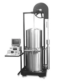
    Gravimetric calibration is one of the most accurate and cost-effective volumetric and gas mass flow meter calibration procedures at low pressure. Piston prover-based gravimetric method is ideal for gases for low flow rates whereas Bell Prover calibration is mainly used for a high flow rate of air calibration. The calibration flow laboratory is always maintained at controlled ambient conditions such as temperature, humidity for master flow meters’ best performance.

    In the piston or bell prover flow meter calibration procedure, a known volume of fluid is forced through a flow meter under test. The piston /bell prover is a cylindrical device with known internal diameter. The piston/bell prover contains a piston/ bell which produces volumetric flow by positive displacement. The piston prover method is ideal for Low flow rate gas or liquid thermal mass flow controller, ultrasonic flow meter & turbine flow meter calibration to a high degree of accuracy.

    Piston / Bell prover Gravimetric calibration steps:
    • Fix the flowmeter in a series of piston/bell prover systems for calibration.
    • Desired gas flow via test flowmeter enters in the piston/bell prover which will move piston/bell upwards with detecting distance between sensors for known volume between is measured.
    • Measuring travel time, pressure, temperature, and flow rate at reference conditions is calculated via software systems.
    • Compare the calculated flow rate with the flowmeter under test and adjust it to the measured flow rate.

    airflow meter calibration

    Critical Flow Venturi ( Sonic Nozzle ) Calibration Procedures

    Critical Flow Venturi Nozzle (Sonic Nozzles) is used for different flow rate capacities designed as per ISO 9300:2015 as a reference standard. Sonic nozzles are considered the best reference standard for calibration of precision flow meters used for custody transfer. Gas flow accelerates to the critical velocity at the throat (known as sonic velocity) where it will reach a steady flow state of single-phase gases. This sonic velocity is a specific point velocity at a certain pressure which is accurate as a reference velocity for calibrating a flowmeter under test. It is used for almost all fixed type flowmeters mainly vortex flowmeter, turbine flowmeter, thermal mass flowmeter, Coriolis flowmeter, etc.

    Sonic nozzle calibration steps:
    • Fix the flowmeter in series of the pipeline where calibrated sonic nozzle
    • Start air compressor in the testing system
    • When sonic velocity reaches the measuring section, the flowmeter under calibration needs to adjust its reading & set it. Repeat the same steps for different sonic velocity points for a specific flow rate.

    Comparing flow rate from a sonic nozzle with flow meter under calibration.

    manufatuerer of air flow meter in india

    Wind Tunnel Calibration Procedures

    The wind tunnel is designed for the characterization of air velocity, air turbulence for various different turbomachinery and instruments calibration and simulation. There are different proprietary & standard designs of wind tunnels installed. It has an open test chamber for calibration or test of the device under test. It is widely used for various types of flow sensor calibration such as hot-wire/vane anemometer, insertion thermal mass flowmeter, pitot tube, measuring probes, etc.

    Wind tunnel calibration steps:

    • Install a flow sensor probe in the test chamber with desired insertion depth and correct orientation.
    • Step by step increasing reference velocity and measure & record flow sensor under test.
    • Based on reference velocity, plot a curve and suitable interpolation & extrapolation flow calculations upload curve into a device under test.

    calorimetric flow meter in india
    thermal mass flow meter in india

    Onsite validation & calibration procedures

    Onsite validation and calibration of gas flowmeters are also possible in some industrial applications. This method is not accurate as the above methods but can validate gas flowmeters in use having high errors or non-repeatability.

    Mainly two ways are possible for onsite validation:

    • Pump-up test with pressure vessel
    • With calibrated reference gas flowmeter to be installed in series

    Pump-up test steps:

    • The pressure vessel in series of gas flowmeter
    • Start Gas flow and note gas flow meter reading and timer for filling a pressure vessel
    • Pressure vessel pressure with respect to volume capacity and gas flow meter totalizer to be compared
    • Validation is done by comparing both results and errors.

    Calibrated reference gas flowmeter:

    • Install calibrated reference gas flowmeter in series of gas flowmeter under validation
    • Compare both flowmeter result and compute the error

    For any technical queries, we would be pleased to provide you related information.

  • 5 Factors that Crucial For Insertion Thermal Mass Flow Meter Performance

    5 Factors that Crucial For Insertion Thermal Mass Flow Meter Performance

    This article talks about the basics of flow profiles, installation criteria, end-user application considerations, and how to use flow conditioning to improve the accuracy of the insertion thermal mass flow meter in areas where a sufficient flow profile isn’t possible.

    insertion thermal mass flow meter

    Number- 1: Understanding velocity profile

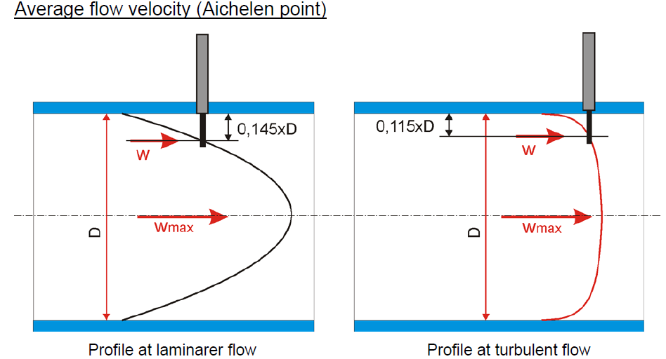
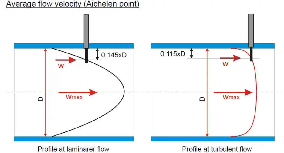
    Inside a pipe, fluids, such as gas, flow at different speeds. When gas flows through a circular pipe, particles in contact with surface of pipe wall come to a halt (W0), forming a boundary layer. To maintain the mass flow rate through the pipe, the gas velocity in adjacent layers slows due to friction and the gas velocity in the midsection increases at centre is (Wmax). The velocity profile is the velocity distribution through the tubing. Fully developed velocity profile is almost parabolic, whereas turbulent profile is almost flat in nature. It is possible to determine velocity anywhere within the pattern by understanding the velocity profile.

    Number- 2: ‘Installation location is critical’​

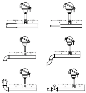
    The location of a flowmeter installation is crucial, but it is often ignored. It’s common to make a location decision solely on the basis of ease of installation. Before putting a flowmeter in place, the end-user should think about the flow disturbances in the region. As a result, consider carefully which site would be the most successful. In any case, once the position ( either vertical or horizontal or inclined ) has been determined, define the disturbances so that the manufacturer can decide if flow conditioning is necessary or not.

    insertion thermal mass flow meter in india
    thermal mass flow meter

    Number- 3: Flow conditioning requirements

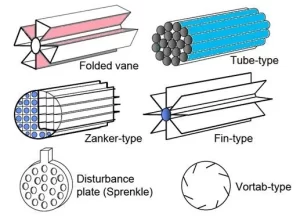
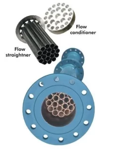
    In industrial processes the flow profile is affected by several disturbances upstream of the flowmeter. If appropriate straight length is unavailable for measurement performance, there is a need to install Flow conditioning device as an option upstream for better performance with less upstream length. Flow conditioners (also known as flow straighteners) may provide a consistent flow profile near the sensor.

    thermal mass flow meter in India leomi

    Number- 4: Process conditions

    In industrial processes flow sensor will be exposed to various process conditions such as temperature & pressure variations, condensation of gases, gas mixtures etc. should be informed to Thermal Mass flow meter manufacturers for consideration for compensating all possible factor while parameterization and calibration to ensure optimal accuracy of the flowmeter.

    Number- 5: Consideration in Flow sensor calibration

    The flowmeter sensor probe should be placed in the wind tunnel velocity chamber with uniform velocity. When using a thermal mass flow meter to measure a gas, it’s critical that the manufacturer understands the process conditions of the end user’s application. This allows the manufacturer to calibrate the instrument to the conditions of the application’s location. Flow rate in-accuracies will occur if this is not done. With a fully automatic calibration wind tunnel flow velocity versus sensor power is measured accurately programmed, to evaluate the relationship between mass flowrate and the signal for the gas and sensor under calibration, this step is repeated several times across the entire range.

    Thermal mass Flowmeter

    Conclusion

    When choosing a thermal mass flowmeter considering the above factors will ensure an optimal accuracy with desired performance.

    LEOMI Instruments from Gandhinagar, INDIA has developed proven technologies and wide-ranging solutions for thermal mass flow meters with recognition of Startup India. A make-in-India with manufacturing facility meeting German technology standards, that allows them to optimize the life of industrial processes, equipment, and machines.

    LEOMI’s products and expertise have helped flow measurement advancement in dozens of industrial applications including compressed air, combustion air, biogas, natural gas, flue gas, aeration air, corrosive process gases, and many more.

    Author: Manish Patel – Director Leomi India

  • India’s first In-house Fully Automatic Air Velocity Calibration as per ISO 17025

    India’s first In-house Fully Automatic Air Velocity Calibration as per ISO 17025

    Are you able to find a reliable manufacturer of Insertion Thermal Mass flowmeter with an In-house calibration facility in INDIA?

    Facing problem in validating/calibration of your existing Insertion Thermal Mass flowmeter, or Air velocity Instruments?

    Calorimetric airflow meter

    THEN, THIS ARTICLE IS FOR YOU.

    LEOMI has developed ways to optimize your existing air & gas flow measurement systems. LEOMI has newly commissioned India’s first in-house latest State-of-the-art Wind Tunnel, Made in Germany for Air Velocity Calibration and anemometer calibration services. It is certified as per ISO-17025 and DAkkS Germany traceability for air flow velocity ranges from 0.2 m/s to 75 m/s with flow uniformity of ±0.2%.

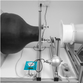
    The wind tunnel is constructed according to the Göttinger-type is a Closed designed circular tunnel with 180mm Nozzle diameter with 320mm open working section. Göttinger-type may be operated optionally using a closed section of measurements. The design requires low blower power and silence than other Eiffel-type wind tunnels.

    CALIBRATION AND TEST IN WIND TUNNEL UP TO 75M/S

    The wind tunnel is equipped with a precise flow calculation system that measures and control all functions as below:

    • the measurement of airflow velocity at the outlet of the nozzle with Prandtl-tube (high velocity) & thermal anemometer (low velocity)
    • Temperature, Relative humidity
    • Barometric pressure

    Flow calculation system uses multiple range differential pressure sensors for measurement of differential pressure across Prandtl type Pitot-static tube. The system uses a barometrical pressure sensor & temperature humidity sensor to calculate the actual density of the air. A special software (Lab View) uses these physical values to calculate the flow velocity at the outlet of the nozzle. For low velocity, a precise low-velocity thermal anemometer is used as a reference which is a switchover as velocity setpoints. The flow calculation system has a USB 2.0 interface to connect it to a computer.

    LEOMI DEVELOPS A PROPRIETARY CALIBRATION SOFTWARE 

    With a wind tunnel flow calculation system, Leomi developed a customized LabView-based calibration software that is capable of

    • measuring all data from wind tunnel flow calculation system via TCP/IP
    • measuring required parameters from the test instrument (Leomi-586) under calibration
    • recording system log of all wind tunnel parameters and test instrument
    • transfer calibration table to test instrument
    • preparing calibration protocol & printed
    • customize for other instruments calibration and test

    This customized software program is for controlling the wind tunnel and taking the measurement values of all sensors, included the calibrated sensor. All data will be completely recorded. Calculated data and status information will also be recorded. All relevant data are shown on the screen and add the calibrating curve. The calibrating is done completely under the control of this program. The curve in the following screenshot is the result of a calibration done completely without any influence of the user. After the calibration, the calculated data could be transferred to the calibrated unit. At last, after the calibration, a protocol will be printed.

    LEOMI a registered #startupindia company by DPIIT Government of India, LEOMI has developed Insertion Thermal Mass (Calorimetric) Flowmeters in India by technology transfer agreement from founders of Softflow.de, Germany. This will greatly help India for its self-sufficiency in such technology demand against import substitutes. Support us by being “Vocal for Local.”

    We just don’t stop here, LEOMI provide support for Air Velocity calibration services of other manufacturers’ product of various types of Air Velocity instruments, such as Insertion Thermal Mass Flowmeter, Hot-wire / Vane Anemometer, L Type & S Type Pitot Tube, etc.