Category: Insertion Thermal Mass Flowmeter

  • Maximizing Efficiency with Insertion Thermal Mass Flow Meters for Bio Gas Flow Measurement

    Maximizing Efficiency with Insertion Thermal Mass Flow Meters for Bio Gas Flow Measurement


    Biogas is a renewable energy source that can be produced from various organic waste materials. To maximize the efficiency of biogas production and ensure optimal energy management, it is crucial to have accurate and efficient compressed biogas flow measurement systems in place.

    One of the most reliable and cost-effective techniques for biogas flow measurement is the insertion of thermal mass flow meters. In this blog post, we’ll explore the advantages of using insertion thermal mass flow meters for biogas flow measurement.


    The Importance of Accurate Biogas Flow Measurement

    The measurement of biogas flow is essential for efficient energy production and management. Accurate compressed biogas flow measurement helps to optimize process control, reduce costs, and ensure safety. Inaccurate measurement of biogas flow can lead to reduced energy output, damage to equipment, and safety hazards.

    Moreover, precise biogas flow measurement is critical for complying with regulatory requirements and ensuring accurate reporting.


    Advantages of Using Insertion Thermal Mass Flow Meters

    Insertion thermal mass flow meters are an excellent choice for biogas flow measurement due to several advantages.

    Firstly, insertion thermal mass flow meters provide high accuracy and repeatability, even in applications with varying gas composition and temperature. They are also insensitive to pressure changes and provide real-time measurement of gas flow rate and totalized flow. It works quite well at too-low static pressure. It is adjustable to various pipe diameters.

    Furthermore, insertion thermal mass flow meters are easy to install, require low maintenance, and do not require additional pressure or temperature compensation devices. Overall, the insertion of thermal mass flow meters provides a cost-effective and reliable solution for biogas flow measurement.


    Best Practices for Using Insertion Thermal Mass Flow Meters for Biogas Flow Measurement

    To ensure accurate biogas flow measurement with the insertion of thermal mass flow meters, it is essential to follow best practices. For instance, the insertion point of the flow meter should be located in a section of the pipe where the flow is fully developed and not affected by turbulence or obstructions.

    The flow meter should also be calibrated regularly and verified against a reference standard. Additionally, proper installation of the flow meter, including orientation and depth, can affect its accuracy and should be carefully considered.


    Applications of Insertion Thermal Mass Flow Meters in Biogas Flow Measurement

    Insertion thermal mass flow meters have a wide range of applications in biogas flow measurement, including biogas plants, landfills, wastewater treatment plants, and agricultural operations.

    In biogas plants, insertion thermal mass flow meters are used to monitor the feedstock and optimize the fermentation process, resulting in increased gas yield and quality. In landfills, insertion thermal mass flow meters are used to monitor the gas generated by organic waste decomposition and ensure compliance with environmental regulations.

    In wastewater treatment plants, insertion thermal mass flow meters are used to monitor the waste gas produced during the digestion process and optimize energy recovery. In agricultural operations, insertion thermal mass flow meters are used to monitor the gas produced from manure and optimize biogas production.


    Conclusion

    In conclusion, insertion thermal mass flow meters are an excellent choice for biogas flow measurement due to their high accuracy, repeatability, and cost-effectiveness.

    Following best practices for installation and calibration can ensure accurate measurement and optimize energy production and management in various industries and applications. Insertion thermal mass flow meters offer a reliable and efficient solution for biogas flow measurement, providing significant benefits for both the environment and the bottom line.

    At Leomi Instruments, we offer a wide range of high-quality insertion thermal mass flow meters for biogas flow measurement. Our products are designed to provide accurate and reliable measurements in various applications, ensuring optimal energy management and compliance with regulatory requirements.

    We also offer expert installation and calibration services, ensuring that our products perform at their best. Contact us today to learn more about our biogas flow measurement solutions and how we can help maximize efficiency in your operations.

  • How to Measure Compressed Air Flow Accurately & Efficiently?

    How to Measure Compressed Air Flow Accurately & Efficiently?


    Compressed Air Flow is a vital resource in various industrial applications from operating pneumatic tools and machinery for performing required functions either in production or processes.

    However, managing compressed air usage can be challenging as it is often one of the most expensive forms of energy used in a facility. One of the key factors in managing compressed air usage is the accurate measurement of compressed air flow rate.


    Why accurate measurement of compressed air is important?

    Accurate measurement of compressed air flow is essential for industrial facilities in several ways.

    1. Optimizing the operation of compressed air systems: By monitoring the flow rate, facilities can identify and correct leaks, adjust compressor settings, and reduce the use of unnecessary air. This can result in significant cost savings, as compressed air is often one of the most expensive energies used in a facility.
    2. Improving Efficiency of equipment and processes: For example, in a paint spray booth, the compressed air flow rate must be carefully controlled to ensure that the paint is applied evenly. If the flow rate is too low, the paint will be poorly atomized and will not be applied evenly. If the flow rate is too high, the paint will be over-atomized, resulting in wasted paint and higher costs.
    3. Compliance with Industry Standards: Accurate flow measurement is also necessary to meet industry standards and regulations, such as ISO 50001 for energy management and OSHA regulations for employee safety.
    4. Leak Detection and Reduction: Accurate flow measurement enables real-time monitoring of compressed air usage and a higher turndown ratio helps to identify and reduce leaks in compressed air systems, reducing energy consumption and costs.
    5. Energy Management: Accurate flow measurement is essential for effective energy management and tracking energy usage in compressed air systems, helping facilities meet energy efficiency targets and reduce costs.


    What is Insertion Thermal Mass Flowmeter?

    Insertion thermal mass flowmeters are nowadays becoming one of the most reliable and accurate ways of measuring compressed air flowrate. These meters use the principle of thermal dispersion to measure the flow of real gases, including compressed air.

    It works on King’s Law where a thermal sensor having two pt-100 sensors one having a heater sensor & another reference sensor that maintains constant differential temperature is installed in a compressed air pipeline. The higher the air mass flow rate higher the cooling effect of the heater sensor which is directly proportional to heater power consumption. The rate of change of mass flow rate is directly related to heater power consumption.

    Insertion thermal mass flowmeters are highly accurate and have a NO pressure drop & higher turndown ratio making them well-suited for use in compressed air systems.


    Conclusion

    Overall, accurate measurement of Compressed Air Flow is essential for optimizing the operation of compressed air systems, improving efficiency, and ensuring the safety of industrial operations.

    Insertion thermal mass flowmeters are an ideal solution for measuring compressed air flow, providing high accuracy and No pressure drop. They are an ideal solution for industrial facilities that want to reduce energy consumption and costs, improve equipment and process efficiency, and ensure the safety of their operations.

    Contact us to accurately measure Compressed Air Flow at your plant.

  • Blast Furnace Gas Flow Measurement in Steel Plant

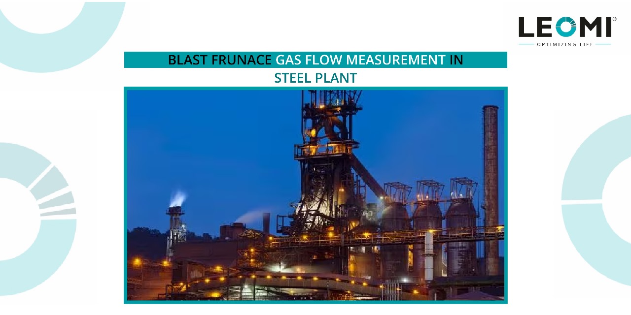
    Blast Furnace Gas Flow Measurement in Steel Plant

    In steel industries Blast furnaces have a key role in smelting iron ore together with fuel (coke) and flux (limestone) continuously supplied from the top of the furnace. Hot blast air with oxygen enrichment is blown into the lower section of the furnace through a series of pipes (tuyeres). This results in chemical reactions while material falls downwards in the furnace.

    Flue gas ( Blast furnace gas) a low calorie will exit from the top of the furnace which in turn is used in other low heating furnaces in other steel processes. Blast furnace gas typically consists of mainly N2(50-55%), CO (20-25%), CO2(16-18%) etc. It contains some moisture content and carbon particle dirt sticky in nature but cleanable.

    Leomi provides a Leomi-586 Insertion Thermal Mass flowmeter which works excellent in these demanding applications against existing Orifice Or Averaging Pitot tube-based DP type flow transmitters.

    The major advantage of Insertion Thermal Mass flowmeter in this application:

    • Measures too low velocity of 0.6m/s or less & No pressure drop
    • Easy installation in minimum time for large pipe diameter
    • Easily removable sensor probe for periodic cleaning when needed

    A major limitation of existing DP-type Flow meter in use:

    • Significant pressure drop limits low flow range measurement
    • Difficult to install and also time-consuming with the high initial cost
    • Non-removable design is difficult for such application

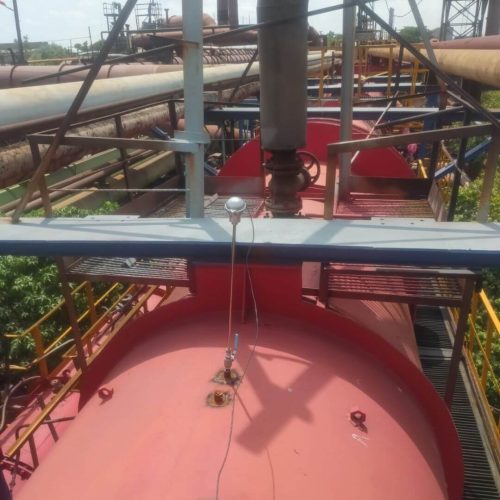
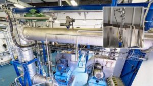
    Leomi-586 Installation in Blast furnace gas application large pipe

  • Advancement in Air & Process Gas Flow Monitoring in Cement Plants for Process Optimization

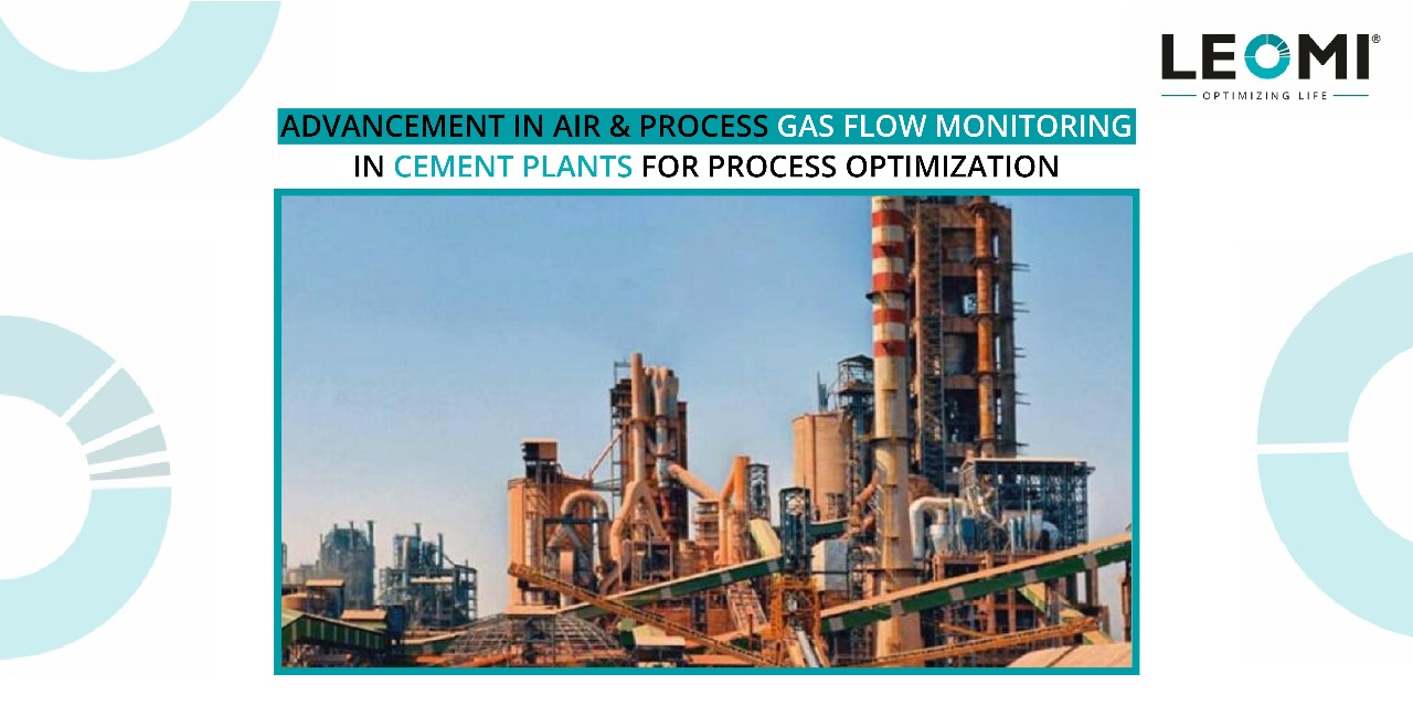
    Advancement in Air & Process Gas Flow Monitoring in Cement Plants for Process Optimization


    Cement Industry is one of the crucial core sectors for the development of construction and infrastructure with currently approx. 4.4 billion Tonnes of cement was produced in the world in the year 2021. The largest cement producer is China with more than 55% capacity and thereafter India accounts for the second largest product with around 7% of capacity.

    After the COVID-19 pandemic, there was a sudden rise in demand from rural and urban infrastructural developments across the world and mostly in undeveloped countries. Initiatives such as the Smart City project by India will see a long-term demand for cement products which will see huge technological upgradation of existing cement plants for cost and energy optimization.

    The cement industry is one of the most intensive energy consumers in the industrial sectors. Energy consumption represents 40% to 60% of production costs. Additionally, the cement industry contributes around 5% to 8% of all man-made CO2 emissions. Due to increasing demand efficiency and optimization will be the key criteria for today’s cement plant operators which will largely depend on the accurate and repeatable measurement of various process parameters such as Temperature, Pressure, Flow Rate & Level, etc.

    In the cement industry generally pressures, temperatures are used for calculating process gas flows in correlation with Fan/Blowers’s speed & power consumption, however, this is an assumption that generates high uncertainties against the actual gas flow rate and energy consumption of prime mover such as Fan/Blowers.

    There is an urgent need for optimum control of Air and process gas flow monitoring for improving the overall quality of cement, efficiency, and cost optimization for many process requirements as below:

    1. PREHEATER PROCESS EXHAUST GAS FLOW RATE MEASUREMENT

    Cyclone Preheaters are used before rotary kilns of cement production plants to heat the raw mix and drive off carbon dioxide and water before it is fed into the kiln. The quality of the preheater in a cement plant directly affects the stability of calcining temperature and cement clinker quality in the kiln. Measuring the exhaust gas flow rate in the downcomer can help in fine control of the ID Fan downstream for optimum control of the O2 content of the kiln off gas.

    Exhaust gas flow measurement generally is challenging due to the large diameter of the duct, high dust concentration, and high temperatures around 350⁰C-400⁰C. Generally, velocity is measured temporarily by Pitot tube with high uncertainties for cross-checking which doesn’t help in the efficient control of the process.

    2. CLINKER COOLER AIR FAN FLOW RATE MEASUREMENT

    The clinker cooler is a key device in the clinker production line which helps in quenching and transports the hot clinkers discharged from the rotary kiln and supplies hot air for the rotary kiln and preheater system. As the first equipment where high-temperature clinker releases heat, it plays an indispensable role in reducing coal and power consumption, increasing secondary and tertiary air temperature, and improving heat recovery rate.

    A good clinker cooler can help cement plants reduce energy consumption from two aspects: one is to improve the cooling efficiency and reduce the power consumption of the clinker cooler itself; the other is to reduce the coal consumption of rotary kiln and preheating systems by improving the heat recovery rate. Clinker cooler grate air fan efficient control is vital in achieving cooling efficiency and energy saving with a higher cooling rate concerning feed rate adjustment. Continuous cooling air flow rate measurement plays an important role in optimizing the operation of a clinker cooler.

    Measurement of a cooler air fan is a challenging task due to the high concentration of clinker dust with a high abrasion rate where flow sensors need to be robust and immune to high abrasion resistance. Currently, this application has a limited flow solution and less life expectancy about 1-6 months.

    3. AQC BOILER & PHP PROCESS GAS OUTLET FLOW MEASUREMENT

    Modern cement plants are equipped with Waste heat recovery (WHR) power plants installed in cement plants, using the heat generated through rotary kiln preheater (PH) and AQC exhaust hot gases for power generation. Waste heat recovery systems (WHRS) wherein hot waste gas heat from rotary kiln preheater & clinker cooler is fed to Preheater (PH) Boiler & After quenching chambers (AQC) boilers to recover heat energy for running boilers for electricity/power generation with the help of steam turbines. Typically, the 20 to 30 percent power requirement of the cement plant can be fulfilled using this waste heat for power generation applications, which is a substantial savings/reduction in the overall cost of production.

    Efficient control of PH & AQC Boiler needs an accurate and reliable inlet or outlet gas flow rate which demands a flow measurement device suitable for high temperature and abrasion resistance design.

    4. PRIMARY AIR FAN FLOW MEASUREMENT IN POWER GENERATION BOILERS

    Cement Plant is installed with Captive Coal Power Plant for fulfilling additional needs of electricity apart from AQC & PH Waste heat recovery Boilers. Primary airflow into the boiler is important to monitor for maintaining optimum stoichiometric air-to-fuel ratio for achieving efficient combustion efficiency. A reliable and accurate primary air flow measurement is needed which has low-pressure drop and works well at low static pressure and low maintenance.

    5. PROCESS & FLUE GAS FLOW MEASUREMENT IN EXHAUST STACK

    Exhaust process flue gas from clinker cooler and boiler needs to be monitored by the pollution control authority for keeping control on emission guidelines is a must. This needs accurate and reliable flow measurement solutions which will help in achieving high thermal efficiency and improve ESP performance & help to regulate harmful pollutants emission controls & provides useful information on optimizing mass balance.

    6. COMPRESSED AIR MEASUREMENT FOR UTILITY CONTROL AND CONSERVATION

    Compressed air is used as a utility in cement plants for the efficient operation of pneumatic equipment used in packing plants and other miscellaneous use needs to be monitored as it is invisible energy as for producing 4 scfm compressed air one horsepower (HP) electrical energy is consumed.
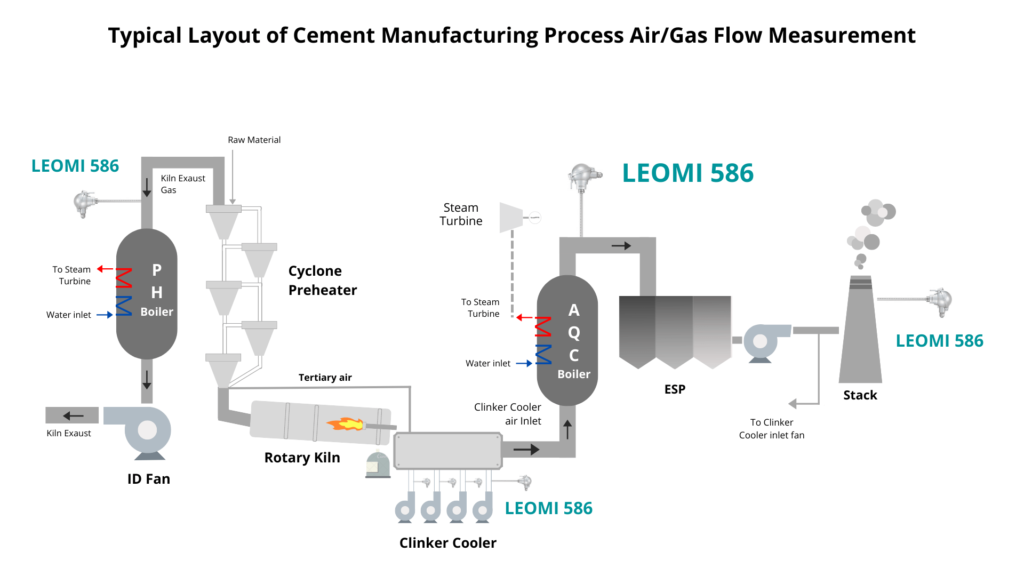
    cement manufacturing process air or gas flow measurement

    An accurate air & gas flow measurement in cement production helps in

    • Reducing Blower (ID/FD Fan) power consumption i.e., energy saving
    • Controlling the accurate and repeatable operation of kiln & improving clinker production quality
    • Improves energy efficiency of Clinker cooler fan & energy conservation

    Major Challenges in existing flow measurement solutions for the above applications

    • High-pressure drop means energy loss
    • Lower turn-down ratio implies limited operational range and leakage insensitive.
    • Lower accuracy & measurement resolution implies limited efficiency & performance analysis
    • Clogging and high wear factor
    • High cost of installation & needs frequent maintenance.

    Overcoming above challenges by advance proven calorimetric (heat dissipation) technology:

    Nowadays Insertion Thermal Mass (Heat dissipation) Flow meter technology is gaining technical ground for solving above limitations of existing conventional pitot tube or annbar differential pressure-based flow measurement.

    Insertion Thermal Mass Flowmeter

    Working Principle

    Thermal mass (calorimetric) flow meters work on the physical principle of thermal dispersion from a heated element to the ambient medium (e.g., air or gases). This is affected by the velocity, density (temperature and pressure) and by the characteristic of the medium. The amount of needed energy is a function of the temperature difference ∆T and the mass flow.

    Gas flowing through two RTD Pt-100 one reference (Tref) and another Heater (Th). The temperature difference (over temperature) ∆t between the reference sensor (medium temperature) and the heater sensor is controlled constant. As per King’s Law, higher the mass flow rate, higher the cooling effect of the heater sensor, thus higher the power required to maintain the differential temperature constant. Therefore, the heater power is proportional to the gas mass flow rate.
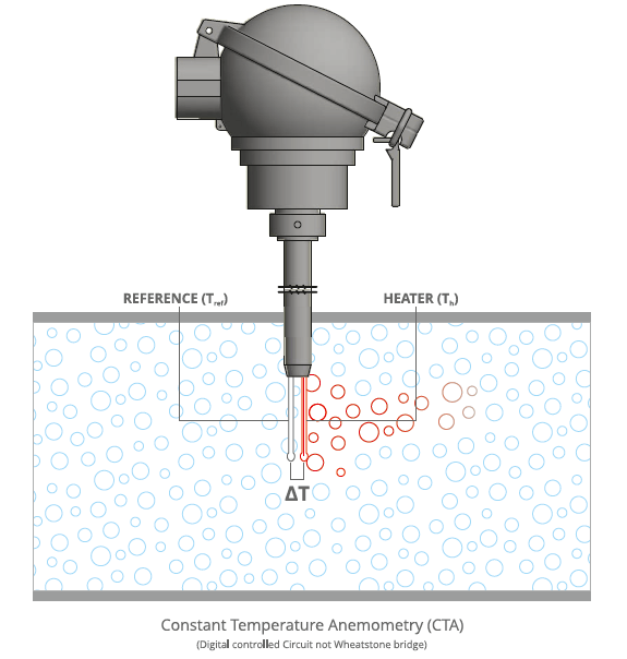
    Advantages of Insertion Thermal Mass Flow metering technology against conventional flow metering

    • Pipe sizes suitable 15mm to 10 metres
    • Easy Installation, orientation & rugged design with customized sensor material design
    • Working temperature upto 400⁰C & 16barg or higher can be achieved
    • Better accuracy < ±2%RD of mass flow rate
    • Highest turn down ratio 100:1 or better, too sensitive throughout flow ranges.
    • No pressure drop saves energy (pressure) loss
    • Versatile & Cleanable sensors (auto-purging) design
    • Can be used with too low upstream straight length with special installation procedure
    • Low cost of ownership against other flow technology

    Conclusion

    Cement plant mainly consists of large duct with blowers (FD & ID Fan) where conventional flow measurement is done with Differential pressure sensor as primary elements such as Averaging Pitot tube, Orifice, Aerofoil etc. which are prone to clogg, insensitive to changes in flow velocity, and considerable pressure drop occurs with lower accuracy is now proved to be overall uneconomical to be used against Insertion Thermal Mass flow ( Heat dissipation technique) metering the latest development after long proven track record.

    Now further development on material compatibility with hot gas having heavy dust concentration and high abrasion are in progress which will satisfy most application demands in cement plants with few limitations of temperature upto 500⁰C. Still above 500⁰C operating temperature conventional technologies still rule the market. Hope this will help cement plant process operators to get benefit by implementing new technology against conventional flow measurement and acknowledge the benefits offered.

    Author

    Mr.Manish S Patel, A Chartered Mechanical Engineer with more than 24 years rich experience in process industries especially in flow measurement with a wide range of applications.

    Request to kindly write us your queries related to the flow measurement applications would be happy to assist at our best. For more information contact us.
  • Important Points to Take Care Before Installation of Insertion Thermal Mass Flow meter

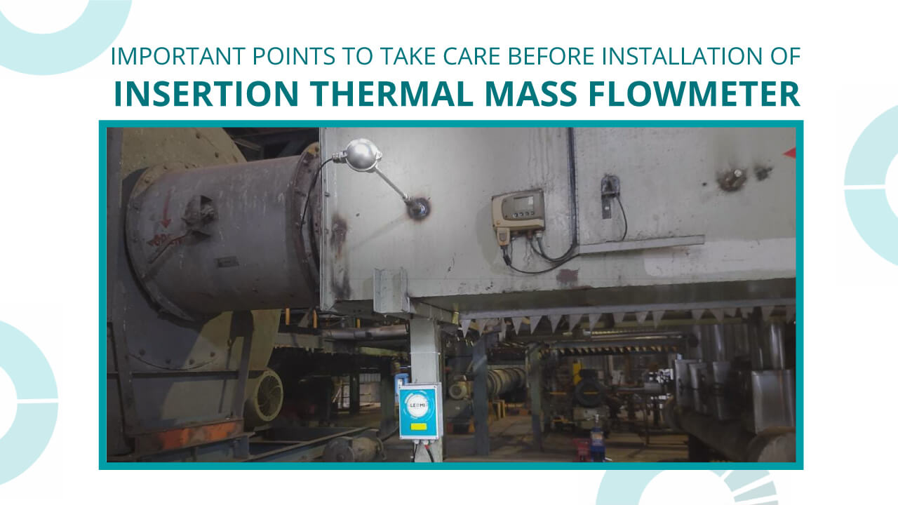
    Important Points to Take Care Before Installation of Insertion Thermal Mass Flow meter

    points to take care before installation of insertion thermal mass flowmeter

    Application Study

    To conduct a site survey for understanding what is the purpose of gas flow measurement based on process conditions. E.g. Flue Gas stack flow measurement in Coal based Thermal Power plant.

    Insertion Thermal Mass Flow Meter Process Conditions

    Confirm fluid properties as below for optimum selection :

    • Standard Gas or gas mixture (total % proportion)
      Is it a real gas such as nitrogen or a gas mixture such as biogas with 75%methane + 15%CO2 + 5% Nitrogen + 3% water vapor + 2%H2S.
    • Specific gravity or Density or molecular weight
      Standard gas such as Nitrogen has specific gravity :1.25 or density :1250 Kg/Nm3
    • Flow rates (minimum, operating, maximum) based on customers process conditions. Flow rates should be at specific temperature & pressure conditions. E.g. Nm3/hr (DIN1343 – 0⁰C & 1.01325bar), Sm3/hr (Standard 20⁰C &1.01325bar OR ISO2533 15⁰C &1.01325bar ) or Actual m3/hr as per operating conditions.

    temperature & static pressure

    • Static pressure (minimum, operating and maximum in barg or suitable units).
      Static pressure of the gas flowing in the pipeline or duct.
    • Temperature (minimum, operating & maximum ⁰C )
      Temperature of the gas flowing in the pipeline or duct.
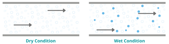
    • Gas conditions such as dry or wet gas or any details of RH% of gas flowing.

    • Gas contains dust or dirt if possible dust concentration in ppm
    • Gas corrosion properties or suitable material compatibility with wetted sensor part
    • Hazardous or Non Hazardous. Identify whether the area of use is hazardous than protection class, zone & gas group classification is needed. ( E.g. Zone I or II Gas group IIA IIB IIC etc). For Non-hazardous Ingress protection such as IP65,IP66,IP67 needed for enclosure & sensor probe housing.

    Mounting

    Confirm accurately below:

    • Pipe dimension: Measure Pipe OD, ID and Thickness OR confirm pipe schedule Sch40,Sch80 etc OR If available Pipe class Class A, Class B or Class C.
    • Duct Size & Type: If Duct is in use check whether it is Square or Rectangular and measure dimensions accurately & Wall thickness
    • Installation location & Mounting Type: Check plant site and identify suitable installation location having desired straight length available. If straight length not available discuss possible practical solutions.
    • With or without isolation valve: If an application demands an isolated sensor probe while running, the process isolation valve needs to be installed or else not.

    Orientation

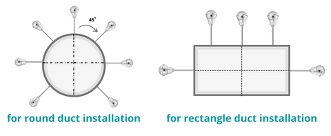
    Identify sensor probe mounting based on space available nearby pipe or duct.

    • Horizontal
    • Vertical
    • Angular based on space available nearby pipe or duct.

    round and rectangle duct installation

    Recommendations

    Check additional points as below:

    • Upstream & Downstream straight length available at mounting site.
    • Power supply conditions
  • PROVIDING FLOW METER TECHNOLOGY WITH IN-HOUSE CALIBRATION

    PROVIDING FLOW METER TECHNOLOGY WITH IN-HOUSE CALIBRATION

    The global flow meter manufacturing industry grew to $8.9 billion in 2020, and it is projected to grow at a CAGR of 5.70 percent till FY2028. The market in India is also expected to see considerable growth due to developments in process automation in various industry core sectors such as Power, water management, chemicals, steel & cement, and more. The global flow meter manufacturing industry grew to $8.9 billion in 2020, and it is projected to grow at a CAGR of 5.70 percent till FY2028.

    The market in India is also expected to see considerable growth due to developments in process automation in various industry core sectors such as Power, water management, chemicals, steel & cement, and more.The global flow meter manufacturing industry grew to $8.9 billion in 2020, and it is projected to grow at a CAGR of 5.70 percent till FY2028. The market in India is also expected to see considerable growth due to developments in process automation in various industry core sectors such as Power, water management, chemicals, steel & cement, and more.

    However, the flow meter industry demands fine-tuning of its process& factory automation which requires products with high accuracy along with a reasonable price range. Manish S. Patel, Director, LEOMI, says, “The primary factor that sets our company apart from the rest of the players in the High-quality Thermal mass flow meter engineered in In­dia for process air and gas flow measurement with various customization options. It is made with German technolo­gy by transfer from softflow.de and has a robust design with a proven track record globally for more than 20 years. We have installed India’s first fully automatic In-house calibration facility & in-house electronic development which provides quick service support to the customers with an affordable pricing range”.


    flow meter manufacturers

    CUSTOMIZED & ENGINEERED PRODUCTS

    Manish adds, “There are large requirements of quality in­ instrumentation with high accuracy and reliability which are currently not available in India forcing the companies to im­port from other countries. Our priority at Leomi is the development of our products into an application based on the expectations of the core sector Industries that we serve, such as power plants and steel & cement as both these industries require customized and engineered products with high accuracy and reliability for their operations. We ensure the quality of our products by meeting all the international standards which are crucial for a product of this type and also helps in exceeding client expectations on performance and reliability”.

    LEOMI started the commissioning of its project along with the establishment of its manufacturing facilities in 2019. It had also recorded a substantial amount of growth in the nuclear, thermal power, steel & textile sector Manish high­ lights, “There is still a lot of room for growth in the Thermal Power sector for flue gas flow measurement and also in the corrosive process gas emissions. We have also exported to Germany, Vietnam, Nigeria to name a few for compressed air and gas” LEOMI is also a registered Start-up India company having an ISO 9001:2015 certification which is a testament to their excellence.

    APPLICATION-ORIENTED PRODUCTS

    LEOMI offers flow meter products that have different types of sensor construction such as stainless steel, Hastelloy C276, HALAR & PFA coatings for a wide range of applications in various industries. The Insertion type of flow meters can be used in an adjustable and versatile manner which is used to monitor multiple locations with a wide temperature range up to 400°C. LEOMI also provides inline flow meters for permanent installation for systemic inspection.

    Manish emphasizes, “Currently our company is working on projects in the power sector which includes the nuclear en­ energy, thermal power generation and for the municipal corpo­ration sewage treatment plant in the aeration air, landfill gas monitoring in the solid waste management process, biogas monitoring process in the food and starch industry.

    LEOMI has developed a perfect tool for compressed air monitoring & recording for energy auditors for conservation initiatives with Thermal mass flowmeter”.

    AIMING FOR OPTIMIZATION

    Manish concludes, “The tagline of our company is ‘Opti­mizing Life’ as a central idea for developing products and solutions which help in optimization of process and equip­ment. Optimization helps in energy conservation in various process industries.

    The company also works on developing import substitute technology products which will support the India program for becoming ATMANIRBHAR (self-re­ learned) by reducing the dependency of importing reliable equipment from other countries”.

  • 5 Factors that Crucial For Insertion Thermal Mass Flow Meter Performance

    5 Factors that Crucial For Insertion Thermal Mass Flow Meter Performance

    This article talks about the basics of flow profiles, installation criteria, end-user application considerations, and how to use flow conditioning to improve the accuracy of the insertion thermal mass flow meter in areas where a sufficient flow profile isn’t possible.

    insertion thermal mass flow meter

    Number- 1: Understanding velocity profile

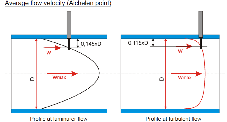
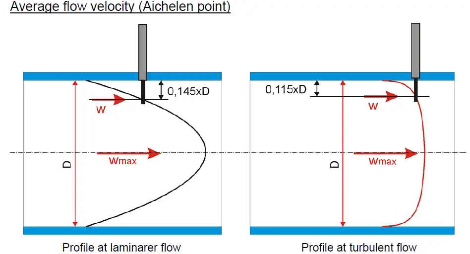
    Inside a pipe, fluids, such as gas, flow at different speeds. When gas flows through a circular pipe, particles in contact with surface of pipe wall come to a halt (W0), forming a boundary layer. To maintain the mass flow rate through the pipe, the gas velocity in adjacent layers slows due to friction and the gas velocity in the midsection increases at centre is (Wmax). The velocity profile is the velocity distribution through the tubing. Fully developed velocity profile is almost parabolic, whereas turbulent profile is almost flat in nature. It is possible to determine velocity anywhere within the pattern by understanding the velocity profile.

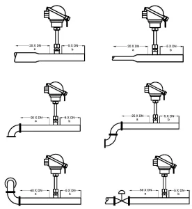
    Number- 2: ‘Installation location is critical’​

    The location of a flowmeter installation is crucial, but it is often ignored. It’s common to make a location decision solely on the basis of ease of installation. Before putting a flowmeter in place, the end-user should think about the flow disturbances in the region. As a result, consider carefully which site would be the most successful. In any case, once the position ( either vertical or horizontal or inclined ) has been determined, define the disturbances so that the manufacturer can decide if flow conditioning is necessary or not.

    insertion thermal mass flow meter in india
    thermal mass flow meter

    Number- 3: Flow conditioning requirements

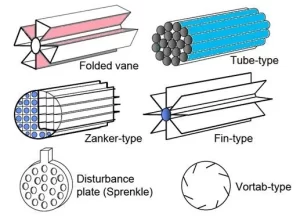
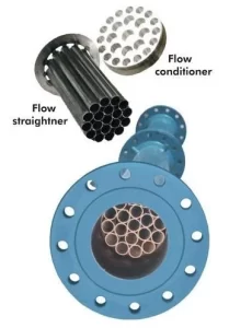
    In industrial processes the flow profile is affected by several disturbances upstream of the flowmeter. If appropriate straight length is unavailable for measurement performance, there is a need to install Flow conditioning device as an option upstream for better performance with less upstream length. Flow conditioners (also known as flow straighteners) may provide a consistent flow profile near the sensor.

    thermal mass flow meter in India leomi

    Number- 4: Process conditions

    In industrial processes flow sensor will be exposed to various process conditions such as temperature & pressure variations, condensation of gases, gas mixtures etc. should be informed to Thermal Mass flow meter manufacturers for consideration for compensating all possible factor while parameterization and calibration to ensure optimal accuracy of the flowmeter.

    Number- 5: Consideration in Flow sensor calibration

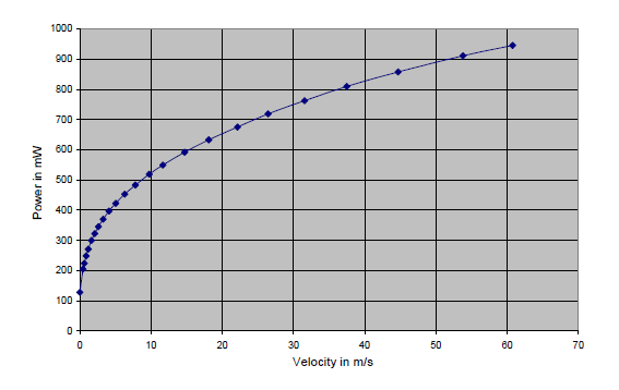
    The flowmeter sensor probe should be placed in the wind tunnel velocity chamber with uniform velocity. When using a thermal mass flow meter to measure a gas, it’s critical that the manufacturer understands the process conditions of the end user’s application. This allows the manufacturer to calibrate the instrument to the conditions of the application’s location. Flow rate in-accuracies will occur if this is not done. With a fully automatic calibration wind tunnel flow velocity versus sensor power is measured accurately programmed, to evaluate the relationship between mass flowrate and the signal for the gas and sensor under calibration, this step is repeated several times across the entire range.

    Thermal mass Flowmeter

    Conclusion

    When choosing a thermal mass flowmeter considering the above factors will ensure an optimal accuracy with desired performance.

    LEOMI Instruments from Gandhinagar, INDIA has developed proven technologies and wide-ranging solutions for thermal mass flow meters with recognition of Startup India. A make-in-India with manufacturing facility meeting German technology standards, that allows them to optimize the life of industrial processes, equipment, and machines.

    LEOMI’s products and expertise have helped flow measurement advancement in dozens of industrial applications including compressed air, combustion air, biogas, natural gas, flue gas, aeration air, corrosive process gases, and many more.

    Author: Manish Patel – Director Leomi India

  • India’s first In-house Fully Automatic Air Velocity Calibration as per ISO 17025

    India’s first In-house Fully Automatic Air Velocity Calibration as per ISO 17025

    Are you able to find a reliable manufacturer of Insertion Thermal Mass flowmeter with an In-house calibration facility in INDIA?

    Facing problem in validating/calibration of your existing Insertion Thermal Mass flowmeter, or Air velocity Instruments?

    Calorimetric airflow meter

    THEN, THIS ARTICLE IS FOR YOU.

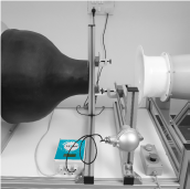
    LEOMI has developed ways to optimize your existing air & gas flow measurement systems. LEOMI has newly commissioned India’s first in-house latest State-of-the-art Wind Tunnel, Made in Germany for Air Velocity Calibration and anemometer calibration services. It is certified as per ISO-17025 and DAkkS Germany traceability for air flow velocity ranges from 0.2 m/s to 75 m/s with flow uniformity of ±0.2%.

    The wind tunnel is constructed according to the Göttinger-type is a Closed designed circular tunnel with 180mm Nozzle diameter with 320mm open working section. Göttinger-type may be operated optionally using a closed section of measurements. The design requires low blower power and silence than other Eiffel-type wind tunnels.

    CALIBRATION AND TEST IN WIND TUNNEL UP TO 75M/S

    The wind tunnel is equipped with a precise flow calculation system that measures and control all functions as below:

    • the measurement of airflow velocity at the outlet of the nozzle with Prandtl-tube (high velocity) & thermal anemometer (low velocity)
    • Temperature, Relative humidity
    • Barometric pressure

    Flow calculation system uses multiple range differential pressure sensors for measurement of differential pressure across Prandtl type Pitot-static tube. The system uses a barometrical pressure sensor & temperature humidity sensor to calculate the actual density of the air. A special software (Lab View) uses these physical values to calculate the flow velocity at the outlet of the nozzle. For low velocity, a precise low-velocity thermal anemometer is used as a reference which is a switchover as velocity setpoints. The flow calculation system has a USB 2.0 interface to connect it to a computer.

    LEOMI DEVELOPS A PROPRIETARY CALIBRATION SOFTWARE 

    With a wind tunnel flow calculation system, Leomi developed a customized LabView-based calibration software that is capable of

    • measuring all data from wind tunnel flow calculation system via TCP/IP
    • measuring required parameters from the test instrument (Leomi-586) under calibration
    • recording system log of all wind tunnel parameters and test instrument
    • transfer calibration table to test instrument
    • preparing calibration protocol & printed
    • customize for other instruments calibration and test

    This customized software program is for controlling the wind tunnel and taking the measurement values of all sensors, included the calibrated sensor. All data will be completely recorded. Calculated data and status information will also be recorded. All relevant data are shown on the screen and add the calibrating curve. The calibrating is done completely under the control of this program. The curve in the following screenshot is the result of a calibration done completely without any influence of the user. After the calibration, the calculated data could be transferred to the calibrated unit. At last, after the calibration, a protocol will be printed.

    LEOMI a registered #startupindia company by DPIIT Government of India, LEOMI has developed Insertion Thermal Mass (Calorimetric) Flowmeters in India by technology transfer agreement from founders of Softflow.de, Germany. This will greatly help India for its self-sufficiency in such technology demand against import substitutes. Support us by being “Vocal for Local.”

    We just don’t stop here, LEOMI provide support for Air Velocity calibration services of other manufacturers’ product of various types of Air Velocity instruments, such as Insertion Thermal Mass Flowmeter, Hot-wire / Vane Anemometer, L Type & S Type Pitot Tube, etc.

  • Technology Advancements in Flow Measurement- Thermal Mass Flow Meter

    Technology Advancements in Flow Measurement- Thermal Mass Flow Meter

    Thermal mass flow meter technology is evolving and removing some of the challenges faced earlier.

    Thermal Mass Flow Meter deploys mainly two design working principles:

    CONSTANT TEMPERATURE ANEMOMETRY

    The constant-temperature sensor design maintains a constant temperature differential between a heated sensor and a reference sensor; the amount of power required to maintain the differential is measured as an indication of the mass flow rate. Constant-temperature thermal mass flowmeter currently popular with features as below:

    • Active
    • High-frequency response
    • The low electronic noise level
    • Immunity from sensor burnout when airflow suddenly drops
    • High rangeability
    • Compatible with various RTD Pt-100 sensors, such as hot thin film, wire wound, etc.
    • Applicability to gas flows

    CONSTANT POWER ANEMOMETRY

    Constant power sensor design maintains constant power between two temperature sensors which will provide a flow rate proportional to the temperature of the gas flows. This design is less popular and very limited usage due to technical limitations as below:

    • Passive, No feedback mechanism for any correction
    • No zero flow stability
    • Slow temperature & velocity response
    • Limited temperature compensation

    Thermal mass flow meter measurement technology is gaining respect in gas mass flow rate measurement in various applications ranging from very low flow rates to ultra-high flow rates accurately with the best turndown ratio, its versatility, ruggedness, no pressure drop, easy installation against some of the conventional technologies such as Orifice, Aerofoil, Pitot-tube, Turbine & Vortex, etc.

    Thermal mass flow measurement is realized in different ways and flowmeter types for satisfying different industrial needs such as

    • Laboratory style (with By-pass principle) for analytical & research purpose for
    • Inline Industrial style for intermediate pipe sizes from 15mm to 150mm generally
    • Insertion style for larger pipe sizes, etc.

    Today’s process industries demand measurement technologies which are fairly priced and will help in optimizing process efficiency for reducing environmental emissions. To meet such demand, the manufacturers are focusing on the research and development of thermal mass flow sensor technology and its solutions concerning application expectations against other technologies.

    For harsh applications customized Insertion Thermal Mass Flow Meters are available. Process gases stack emissions are corrosive. Chemical industries have to follow emission norms and measure the flow for this. It is impossible to measure the flow with conventional technologies. This has many challenges in measurement such as material compatibility & cost of ownership.

    Manufacturers like LEOMI offer the following solutions

    • HALAR® (ECTFE) coated for corrosive gases up to 100°C (max) and
    • PFA Coated for Hot flue gas & corrosive process gases up to 200°C (max)

    These advancements are an alternative to costlier Hastelloy C276 Insertion thermal mass flow meter made or other special metal grades if any.

    Other air flow meter advancement includes solutions for hot application with corrosive fumes, unknown waste-gas and gas traces in large duct with low-pressure gas mass flow measurement

    FOR MORE INFORMATION ON THERMAL MASS FLOW MEASUREMENT, YOU MAY CONTACT LEOMI.
  • LEOMI 586 vs Thin Film Flow sensor

    LEOMI-586 THERMAL FLOW SENSOR OR THIN-FILM FLOW SENSOR TECHNOLOGIES?? CHOOSE WISELY!

    There are various types of thermal flow velocity sensors available in markets based on proprietary designs concerning application requirements and customer price expectations.

    The thermal mass flow meter sensor uses RTD Pt-100 elements for measuring flow velocity.

    Mainly two types of RTD Pt-100 elements are used to produce thermal flow sensor:

    • The platinum wire of a ceramic wire-wound RTD Pt100 sensor is wound into a small coil that is inserted into the holes of a high purity alumina tube. The ODs of these high purity alumina tube varies from 0.8 mm to 4.5 mm, so they are even suitable for the thinnest RTD mineral insulated cables. It is quite expensive than thin-film resistors.
    • Thin-film RTDs are platinum elements that are constructed by placing a sensing platinum layer over a ceramic substrate, covered with passivation glass layers. This results in excellent shock and vibration resistance and protects the Pt sensor element from environmental influences. It is quite cheaper than ceramic wire wound resistors.

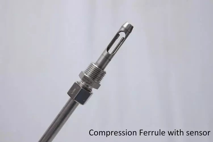
    Leomi-586 uses a ceramic wire wound RTD Pt-100 sensor with a specialized encapsulation process for the best performance for almost every type of application.

    Customer’s process conditions determine which type of thermal flow sensor is better for the application as each has its pros and cons.

    LEOMI-586 FLOW SENSOR ADVANTAGES USING CERAMIC WIRE-WOUND RESISTORS

    • High accuracy better than ±1.5% of reading of along the entire temperature range
    • High dynamic range & resolution
    • Wide temperature ranges -40°C to 500°C
    • Designed with lead length compensation
    • High powered & high differential temperature ranges possible
    • Rugged & drift-free
    • Unaffected by moisture, dirt

    LEOMI-586 FLOW SENSOR DISADVANTAGES USING WIRE-WOUND RESISTORS

    • Larger footprint in length up to 25mm
    • Highly expensive than flow sensor made from thin-film resistors

    THERMAL FLOW SENSOR ADVANTAGES USING THIN-FILM RESISTORS

    • Compact size (around 3mm, or 1/8-inch) in length
    • Vibration resistance due to smaller mass and size
    • Tip-sensitive sensor construction
    • Cheaper than a ceramic wire-wound flow sensor

    THERMAL FLOW SENSOR DISADVANTAGES USING THIN-FILM RESISTORS:

    • Loss of accuracy ±3% of reading at low and high temperatures
    • Works up to 60°C temperatures
    • Low power and low differential temperature range
    • Lower dynamic range & resolutions
    • High drift due to moisture, dirt, and dust
    • No lead length compensation

    FIND HERE, WHY YOU SHOULD CHOOSE LEOMI-586 OVER OTHER THIN FILM FLOW TECHNOLOGIES???

    LEOMI to serve various process industries rugged application developed various types of thermal flow sensors in SS-316Ti, Haste alloy C276, HALAR® coated, PFA coated construction to meets challenging demands. It has robust construction & a rugged flow-sensor design with Pt-100 RTD ceramic wire-wound sensor which provides stable output non-drift, vibration resistant encapsulation, and mechanically strong than thin-film flow sensor.

    Leomi with proven design from (formerly SF-586b) Leomi-586 Insertion Thermal mass flow meter utilizes a combination of an analog controller for high resolution & quick action and digital controller for very high absolute accuracy and long-term stability against the disadvantages of a wheat stone bridge.

    Compression-Ferrule-with-air flow sensor

    LEOMI 586 thermal mass flow sensor with all above merits a preferred choice for any simple or rugged application with accurate, repeatable & stable than thin-film flow sensor. LEOMI provides sensors that can be easily operated even in corrosive gases with HALAR®& PFA coatings upon requests.

    For any queries drop us an email will be happy to assist you.

    From simple airflow velocity transmitter at room conditions needs economical design which uses thin-film resistors whereas application such as hot air or flue gas demands for rugged flow velocity sensor design which has many other technical considerations of high temperature, corrosion, dirt, moisture, dust to be taken into account for performance.

    Thin film-based flow sensors are used bare & un-capsulated whereas Leomi-586 flow sensor used for harsh process gases used with various metallic encapsulated for their long term performance.

    Economical thin-film flow sensors are mainly used for ventilation air, compressed air which is low powered sensor generally flow velocity measurement is done with wheat stone bridge circuitry arrangement which is prone to electrical drifting, no lead length compensation, difficult adjustment of sensors apart from this corrosion due to moisture, sensor drift due to dirt, mechanical vulnerability and many more. So, it ultimately affects the stability, accuracy & life of the flow sensor.